EasyManuals Logo

SICK VMS6200 User Manual

SICK VMS6200
84 pages
To Next Page IconTo Next Page
To Previous Page IconTo Previous Page
Page #35 background imageLoading...
Page #35 background image
ELECTRICAL INSTALLATION 5
35
80251340/2020-02-03|SICK
Subject to change without notice
5.3 Factory connections
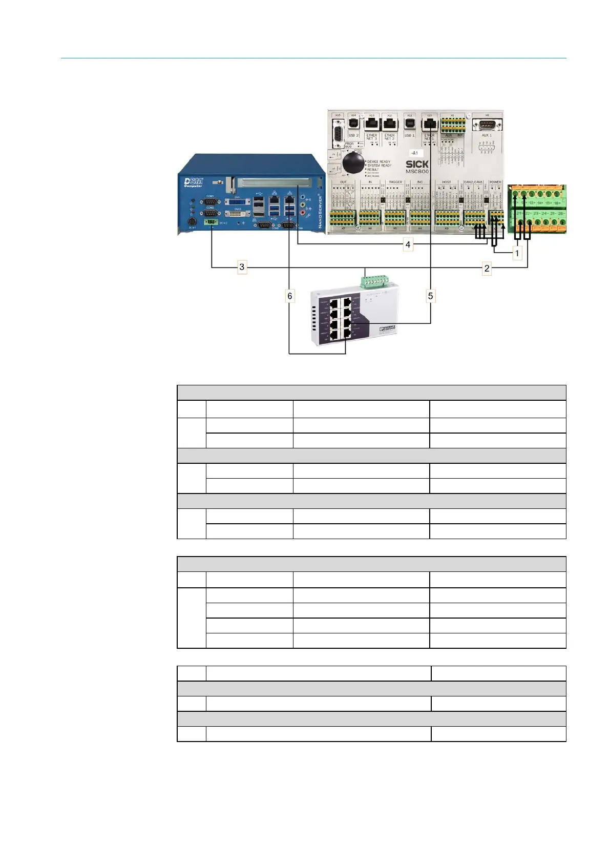
Fig. 25: Factory connections
Power supply MSC800
No.
Wire color Fuse block Connection
1
Red F1_6A 11 +
Dark blue
F1_6A
21
Voltage supply to the Ethernet switch
2
Red
F1_6A
12 +
Dark blue F1_6A 22
Power supply VMC800
3
Red
F1_6A
12 +
Dark blue F1_6A 22
VMC800 --> MSC800 CAN connection
No.
Wire color Terminal block Connection
4
White
X2 CAN 1
10
Blue
X2 CAN 1
11
Black
X2 CAN 1
12
SH X1 POWER 8 SHIELD
No. Connection to the Ethernet switch Port on MSC800
MSC800 Ethernet connection
5
X7
X10
VMC800 Ethernet connection
6 X8 GBit LAN
Tab. 2: Factory connections

Table of Contents

Questions and Answers:

Question and Answer IconNeed help?

Do you have a question about the SICK VMS6200 and is the answer not in the manual?

SICK VMS6200 Specifications

General IconGeneral
BrandSICK
ModelVMS6200
CategoryMeasuring Instruments
LanguageEnglish

Related product manuals