ELECTRICAL INSTALLATION 5
Subject to change without notice
TRANSLATION OF THE ORIGINAL OPERATING INSTRUCTIONS| VMS6200
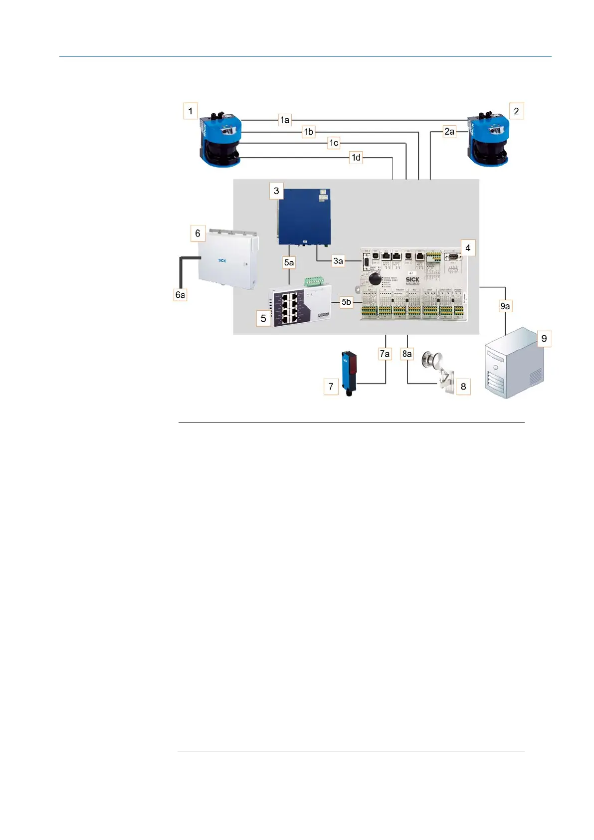
5.1 Connection overview
Fig. 23: Connection overview for the VMS6200
1 Volume measurement device (master)
1a CAN bus
1b Increment
1c CAN bus
1d Ethernet
2 Volume measurement device (slave)
2a Ethernet
3 VMC800 volume measurement controller
3a VMC800 --> MSC800 CAN bus
4 MSC800 system controller
5 Ethernet switch
5a Ethernet connection to the VMC800
5b Ethernet connection to the MSC800
6 Cabinet
6a Feed 100 ... 264 V AC / 50 ... 60 Hz
7 Photoelectric retro-reflective sensor
7a Trigger signal
8 Incremental encoder
8a Incremental signal
9 Customer’s system
9a Data output over Ethernet, fieldbus, or serial connection