4 MOUNTING
TRANSLATION OF THE ORIGINAL OPERATING INSTRUCTIONS| VMS6200
Subject to change without notice
The female and male connectors of the system plug are delivered with covers screwed on.
▸
Screw the cover off the required connections.
▸
NOTE! In the case of the LMS500 that receives the incremental encoder signal, also
screw of the cover from the Increment female connector (this is the master LMS, or the
sensor on the right in the conveying direction).
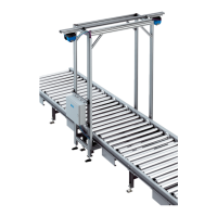
4.2 Mounting the photoelectric retro-reflective sensor
Fig. 20: Mounting the photoelectric retro-reflective sensor
▸
Mount the photoelectric retro-reflective sensor at a minimum distance of 300 mm
upstream of the scan line of the volume measurement devices.
▸
Mount the reflector on the opposite side.
Align the photoelectric sensor correctly on the reflector. The reflector must be in line
with the beam path of the photoelectric retro-reflective sensor.
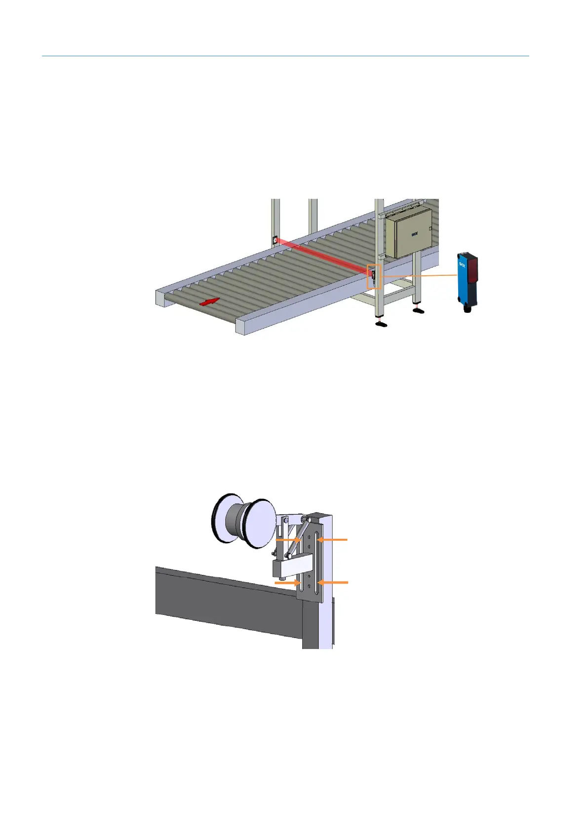
4.3 Mounting the incremental encoder
Fig. 21: Attaching the incremental encoder to the conveying equipment
▸
Install the incremental encoder directly on the conveying equipment.
▸
Tightly screw the incremental encoder to the mounting bracket.
Align the incremental encoder so that it is plane-parallel with the reference plane
(base of the conveying equipment).
Screwing off the
connector covers
Mounting
Mounting