ELECTRICAL INSTALLATION 5
Subject to change without notice
TRANSLATION OF THE ORIGINAL OPERATING INSTRUCTIONS| VMS6200
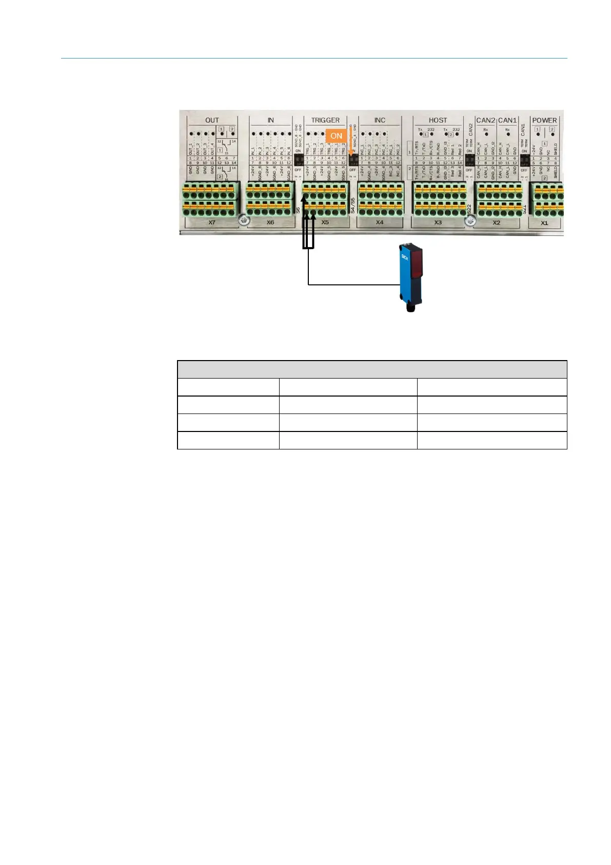
5.5 Connection for the photoelectric retro-reflective sensor
Fig. 27: Connection for the photoelectric retro-reflective sensor
Trigger signal
Wire color MSC800 terminal Connection
Black X5 TRIGGER 1 TRG_1
Brown X5 TRIGGER 7 24 V
Blue X5 TRIGGER 8 SGND_5
Tab. 5: Connection for the photoelectric retro-reflective sensor
▸
Set the DIP switch SGND _5 - GND to ON. This establishes a connection with the GND
of the controller.