5 ELECTRICAL INSTALLATION
TRANSLATION OF THE ORIGINAL OPERATING INSTRUCTIONS| VMS6200
Subject to change without notice
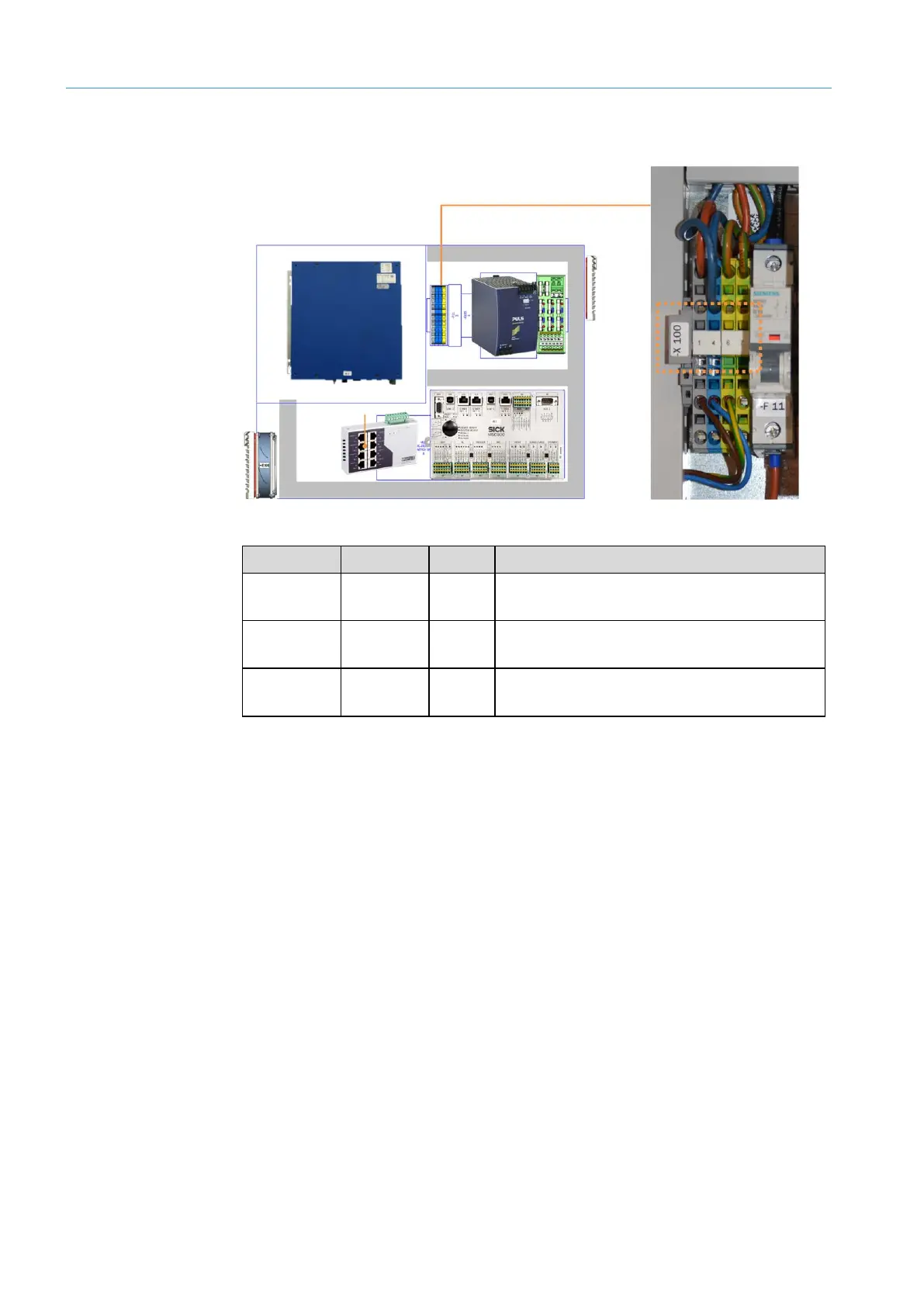
5.2 Connection to the voltage supply
Fig. 24: Pin assignment of the -X100 terminal block in the cabinet
Terminal Color Signal Function
-X100/1.1 Gray L Line voltage 100…264 V AC /
50…60 Hz (phase)
-X100/1.4 Blue N Line voltage 100 ... 264 V AC /
50 ... 60 Hz (neutral conductor)
-X100/1.6 Green-
yellow
PE Protective conductor
Tab. 1: Pin assignment of the -X100 terminal block in the cabinet
NOTE!
▸
Make sure that cables are securely connected.
No visible metal surfaces are permitted on the wires.
▸
Tighten the coupling nuts to provide strain relief on the cabinet. Doing so also
maintains the enclosure rating.