3 SYSTEM DESCRIPTION
TRANSLATION OF THE ORIGINAL OPERATING INSTRUCTIONS| VMS6200
Subject to change without notice
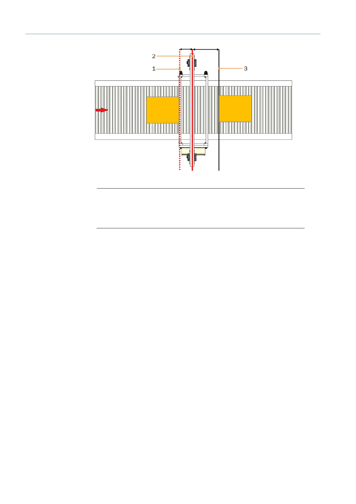
Fig. 15: Trigger and time of data output
Legend
1 Trigger line (e.g., photoelectric retro-reflective sensor)
2 Scan line of the volume measurement devices
3 Earliest data output time
• The minimum distance between the trigger line and the scan line of the two LMS500
sensors is 300 mm.
• The earliest that the calculated dimensions are sent to downstream systems is at a
point 300 mm +200 ms past the scan line.
▸
Make sure that the LMS500 has a clear view of the conveying equipment.
• The LMS500 must be far enough away from bends, induction lines, start/stop areas,
areas with upward and downward slopes, and breaks in the conveying system.
• No side guards are to be mounted in the vicinity of the scan lines.
• The incremental encoder should – if possible – be mounted in the immediate vicinity of
the scan line of the volume measurement devices.
Mounting
the trigger
Optimizing the
scan result