EasyManua.ls Logo

Siemens SIMATIC IPC647E

Siemens SIMATIC IPC647E
200 pages
To Next Page IconTo Next Page
To Previous Page IconTo Previous Page
Loading...
Hardware description
A.2 Internal interfaces
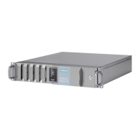
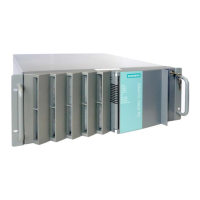
SIMATIC IPC647E
168 Operating Instructions, 11/2018, A5E45589180-AA
A.2.7 Power supply fan monitoring
Pin
Name
Meaning
1
Reserved
-
2 Reserved PWM,
speed setting ATX AC-SV
3
Reserved
-
4 Tacho signal Input monitoring signal
5
PS_Status
Input status of redundant PS
6
Reserved
Reserved for fan failure of redundant PS
7 Quittung_Status Output; Acknowledgment of acoustic alarm signal of redundant
power supply (signal is open when module is switched on)
8
Ground
-
A.2.8 Fan port
Pin
Name
Meaning
1
GND
Ground
2
VCC
+12 V fused
3
Tacho signal
Input monitoring signal
4
PWM
Output speed setting
A.2.9 Supply for the serial ATA drives
Pin
Name
Meaning
1
+12 V
Output power supply
2
GND
Ground
3
GND
Ground
4
+5 V
Output power supply
5
+3.3 V
Output power supply

Table of Contents

Other manuals for Siemens SIMATIC IPC647E

Related product manuals