Hardware description
A.3 Bus board
SIMATIC IPC647E
Operating Instructions, 11/2018, A5E45589180-AA
173
A.3 Bus board
A.3.1 Expansion card slots on the bus board
The bus boards are designed as riser cards The function of these rise cards is spatial
deflection of the plug-in connectors between the motherboard and expansion cards. Thus,
the bus boards are vertically arranged, and the expansion cards are arranged parallel to the
motherboard.
For identification the slots are numbered consecutively and visibly from 1 - 4 on the device
rear panel, see Rear of the device (Page 19).
Depending on your device configuration, one of the following bus board versions is built into
your device.
When inserting PCI/PCIe cards, adhere to the slot specification. 3rd generation PCIe slots
(Gen 3) are, with the same number of lanes, nearly twice as powerful as 2nd generation
slots (Gen. 2).
Bus boards are available in three versions.
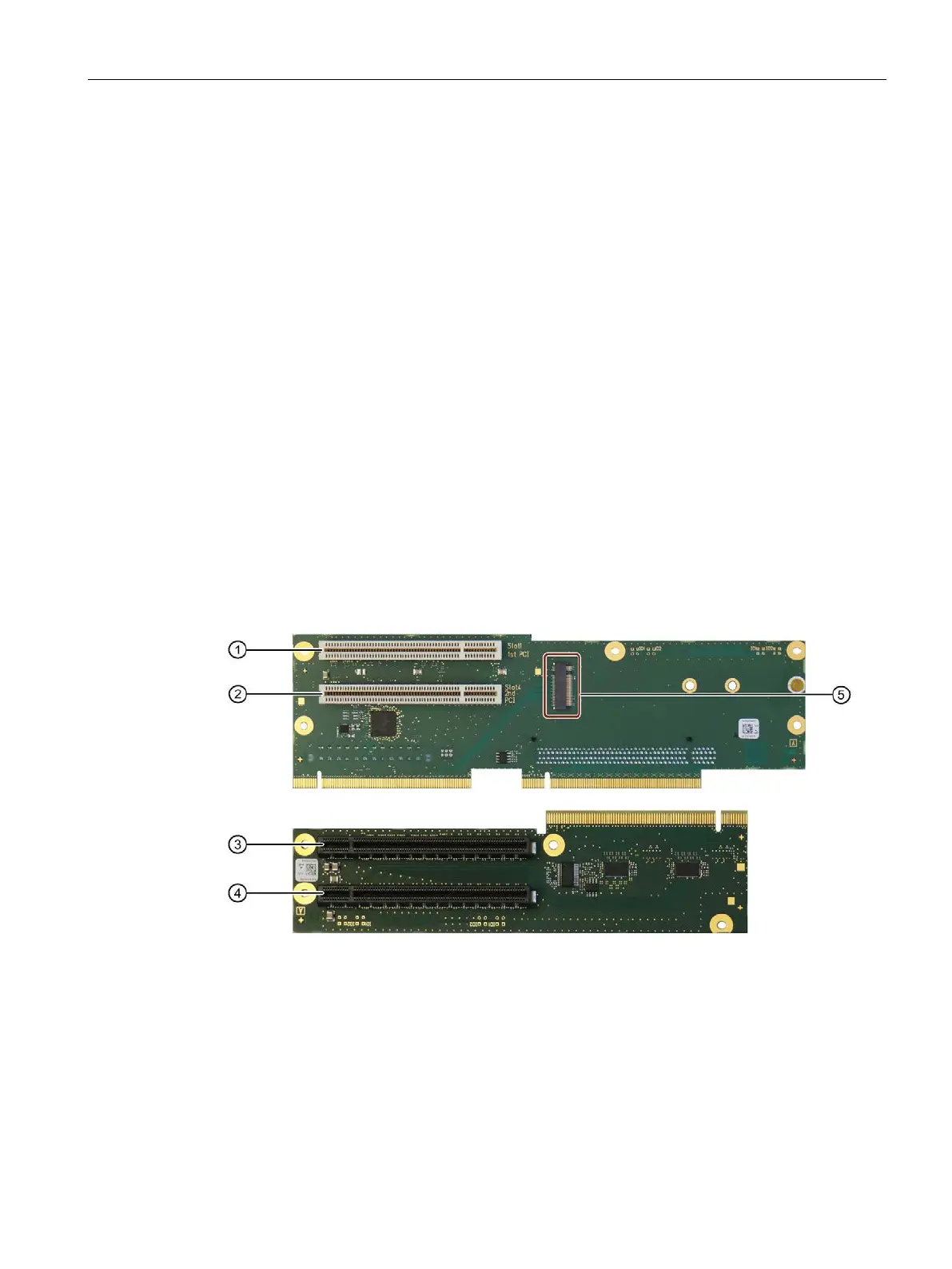
Variant 1: 4-slot, 2 x PCI, 2 x PCIe / with piggyback
The following figure shows the bus board on top and the piggyback on the bottom.
Associated name on the rear of the device: Slot 1
Associated name on the rear of the device: Slot 4
8 x PCIe x16 (8 lanes) slot; piggy-
Associated name on the rear of the device: Slot 3
8 x PCIe x16 (8 lanes) slot; piggy-
Associated name on the rear of the device: Slot 2
Slot M.2 NVMe PCIe Key M x4 (4
Slot 5; internal