07.97 6 NC Machine Data (NC MD), NC Setting Data (NC SD)
6.4 Axis-specific MD 1 (axial data 1)
1st measuring system connection (as from SW 3)
200*
Default value Lower input limit Upper input limit Units
0 +0
15021015 (up to SW 4)
30021030 (as from SW 5)
–
Active on
Power On
07 6 5 4 3 2 1Digit No.
0 1 0 1 1 0 0 0
a
a
a
a
a
a
a
a
a
a
a
a
a
a
a
a
a
a
a
a
a
a
a
a
a
a
a
a
a
a
a
a
a
a
a
a
a
a
a
a
a
a
a
a
a
a
a
a
a
a
a
a
a
a
a
Logical
drive no.
(611-D)
a
a
a
a
a
a
a
a
a
a
a
a
a
a
a
a
a
a
a
a
a
a
a
a
a
a
a
a
a
a
a
a
a
a
a
a
a
a
a
a
a
a
a
a
a
a
a
a
a
a
a
a
a
a
a
a
a
a
a
a
No. of 611-D
servo loop
connection
a
a
a
a
a
a
a
a
a
a
a
a
a
a
a
a
a
a
a
a
a
a
a
a
a
a
a
a
a
a
a
a
a
a
a
a
a
a
a
a
a
a
a
a
a
Code
digital
drive
a
a
a
a
a
a
a
a
a
a
a
a
a
a
a
a
a
a
a
a
a
a
a
a
a
a
a
a
a
a
a
a
a
a
a
a
a
a
a
a
a
a
a
a
a
a
a
a
a
a
a
a
a
a
a
a
a
a
a
a
a
a
a
a
a
a
a
a
a
a
a
a
a
a
a
a
a
a
a
a
a
a
a
a
a
a
a
a
a
a
a
a
a
a
a
a
a
a
a
a
a
a
a
a
a
a
a
a
a
a
a
a
a
a
a
a
a
a
a
a
a
a
a
a
a
a
a
a
a
a
a
a
a
a
a
a
a
a
a
a
a
a
a
a
a
a
a
a
a
a
a
a
a
a
a
a
a
a
a
a
a
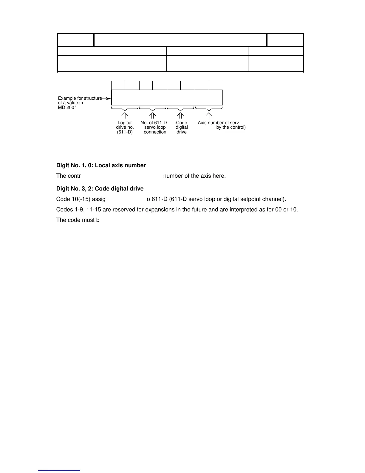
Axis number of servo loop module
(entered by the control)
Example for structure
of a value in
MD 200*
Digit No. 1, 0: Local axis number
The control automatically enters the local number of the axis here.
Digit No. 3, 2: Code digital drive
Code 10(-15) assigns the address to 611-D (611-D servo loop or digital setpoint channel).
Codes 1-9, 11-15 are reserved for expansions in the future and are interpreted as for 00 or 10.
The code must be entered by the user.
Digit No. 5, 4: SPC/HMS setpoint output
Permissible values for digital drives are the values 01 and 02:
01: PCU slot 1 (for MSD permanent indirect measuring system)
02: PCU slot 2 (free direct or indirect measuring system)
Digit No. 7, 6: Logical drive number / Servo loop module number
The logical drive number is entered here for digital drives.
Input range (00..15): 00: No submodule available
01..15: According to logical drive number
For more detailed information see MDD
Input range (00..30): 00: No submodule available
(SW 5 and higher) 01..30: Logical drive number
Notes:
• See Section 5, Machine Data Dialog, for the servo loop assignment.
• Up to SW 4: Only 14 real axes can be defined with a fictitious axis.
©
Siemens AG 1992 All Rights Reserved 6FC5197- AA50 6–37
SINUMERIK 840C (IA)