09.95
Siemens AG 2001 All Rights Reserved 6FC5197–jAA50
9–64
SINUMERIK 840C (IA)
9.6 SERVO trace (SW 4)
Explanation To supplement the start-up functions “DAC output” and “Measurement function”
implemented in SW 3, SW 4 includes a trace function with the following function-
ality:
S 4 trace buffers with 2048 values
S Output of SERVO signals with symbolic signal selection
S Graphic representation of recorded signal waveforms
S Various trigger conditions for starting recording
S Pre-trigger and post-trigger settings possible
S File functions for storing and loading trace settings and measurement curves
The SERVO trace function is integrated on the highest menu tree level of the
drive servo start-up application since the 4 trace buffers offer 4 global resources
which can be applied to any NC axis or spindle (comparable to the 4 DAC chan-
nels of the mixed I/O module).
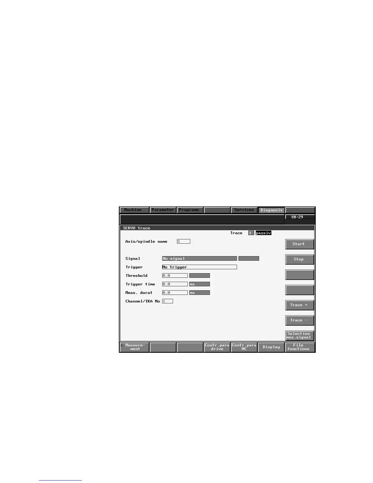
Selection The SERVO trace display can be called by means of softkeys Diagnosis,
Start-up and Drive servo startup.
Fig. 9.35
Explanation The measurement parameters relevant to the trace function can be set in this
display.
The field marked “Signal” is a pure output field which indicates the measured sig-
nal selected under softkey Selection meas.signal. The text “No signal” is the
default setting.
9 Drive Servo Start-Up Application (as from SW 3)
9.6 SERVO trace (SW 4)