12 Functional Descriptions 07.97
12.18.11 GI monitors
12.18.11.2 Fine/coarse synchronism
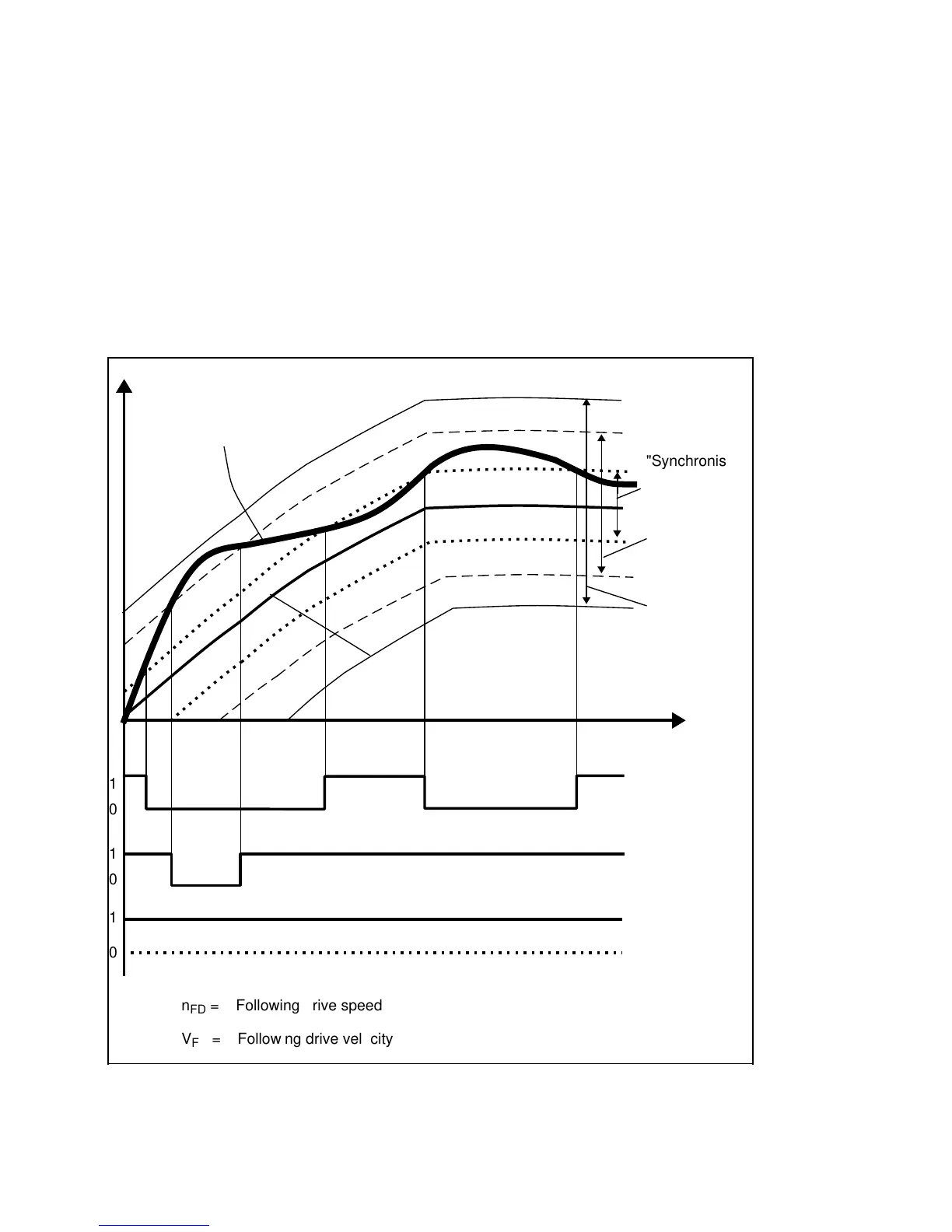
In the LINK ACTIVE state, the interface signal SYNCHRONISM FINE or SYNCHRONISM
COARSE indicates that the present setpoint position and setpoint velocity of the following drive
is within the tolerance window specified by means of machine data.
For this purpose, the deviation of the following axis from its setpoint path is continuously
measured in the LINK ON state and checked against the two tolerance windows
"SYNCHRONISM COARSE" (NC MD 1440*492*) or "SYNCHRONISM FINE" (NC MD
1436*/491*). If the deviation exceeds the permissible tolerance limit, the associated PLC
interface signal is set to 0.
These interface signals make it possible to control the process sequence as a function of the
synchronized state of the following drive from the PLC user program. For example, it is
possible to delay enabling of the hobber feed until the NS SYNCHRONISM signal is present.
Synchronism monitoring in LINK ON state
n
FD
(V
FD
)
t
a
a
1
a
a
0
a
a
1
a
a
0
a
a
1
a
a
a
0
n
FD
= Following drive speed
V
FD
= Following drive velocity
"Synchronism
fine" tolerance
band
"Synchronism
coarse" tole-
rance band
"Emergency
retraction"
tolerance
window
NS SYNCHRO-
NISM FINE
"Emergency
retraction"
hardware signal
n
FDs e t
n
FDa c t
NS SYNCHRO-
NISM COARSE
12–146
© Sie me ns AG 1992 All Right s Re s e rve d 6FC5197- AA50
SINUMERIK 840C (IA)