09.01 12 Functional Descriptions
12.18.11 GI monitors
n
FA
Tipo
Tipo
a
a
a
a
a
a
a
a
a
a
a
a
a
a
a
a
a
a
a
a
a
a
a
a
a
a
a
a
a
a
MD 336<>0
a
a
a
a
a
a
a
a
a
a
a
a
a
a
a
a
a
a
a
a
a
a
a
a
MD 336=0
V
set
V
act
Tipo
a
a
a
a
a
a
a
a
a
a
a
a
a
a
a
a
a
a
a
a
a
a
a
a
a
a
a
a
Leading axis
v
LA
a
a
a
a
a
a
v
set
a
a
a
a
a
a
a
a
a
a
a
a
a
a
a
a
a
a
a
a
a
a
a
a
a
a
a
a
a
a
v
set
· MD335
a
a
a
a
a
a
a
a
a
a
a
a
a
a
a
a
a
a
a
a
a
a
a
a
a
a
a
a
a
a
a
a
Following axis
a
a
a
a
a
a
a
a
a
a
a
a
a
a
a
a
a
a
a
a
a
a
a
a
a
a
a
a
a
a
a
a
a
a
a
a
a
a
a
a
a
a
a
a
a
a
a
a
a
a
a
a
a
a
a
a
a
a
a
a
a
a
a
a
a
a
a
a
a
a
a
a
a
a
a
a
a
a
a
a
a
a
a
a
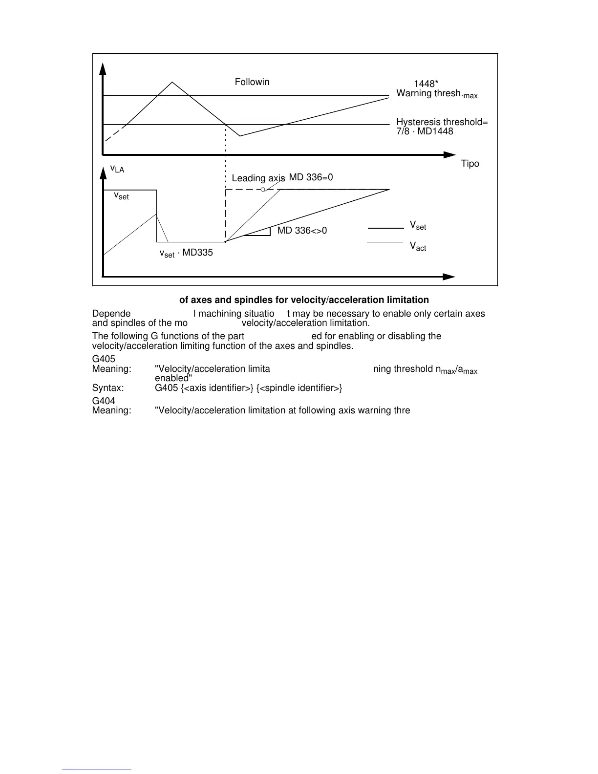
MD 1448*
Warning thresh.
max
a
a
a
a
a
a
a
a
a
a
a
a
a
a
a
a
a
a
a
a
a
a
a
a
a
a
a
a
a
a
a
a
a
a
a
a
a
a
a
a
a
a
a
a
a
a
a
a
a
a
a
a
a
a
a
a
a
a
a
a
a
a
a
a
a
a
a
a
a
a
a
a
a
a
a
a
a
a
a
a
a
a
a
a
a
a
a
a
a
a
a
a
a
a
a
a
a
a
a
a
a
a
a
a
a
a
a
a
a
a
a
a
a
a
a
a
a
a
a
a
a
a
a
a
a
a
a
a
a
a
a
a
a
a
a
a
a
a
a
a
a
a
a
a
a
a
a
a
a
a
a
a
a
a
a
a
Hysteresis threshold=
7/8 · MD1448*
Enabling/disabling of axes and spindles for velocity/acceleration limitation
Dependent on the actual machining situation, it may be necessary to enable only certain axes
and spindles of the mode group for velocity/acceleration limitation.
The following G functions of the part program are used for enabling or disabling the
velocity/acceleration limiting function of the axes and spindles.
G405
Meaning: "Velocity/acceleration limitation at following axis warning threshold n
max
/a
max
enabled"
Syntax: G405 {<axis identifier>} {<spindle identifier>}
G404
Meaning: "Velocity/acceleration limitation at following axis warning threshold n
max
/a
max
disabled"
Syntax: G404 {<axis identifier>} {<spindle identifier>}
Remark: G404 without axis/spindle identifier means that all axes/spindles of the mode
group are blocked
G group: 20
Internal coding: G404=7, G405=8
G functions must be programmed separately in one block.
A maximum of 5 axes and 1 spindle can be programmed in one block. Enabling/disabling the
axes is effected additively, i.e. the status of non-programmed axes/spindles remains
unchanged.
Note:
On ELG chaining, the first leading axis of the chain, and possibly all following axes working in
following axes override mode, must be enabled.
Example:
The chaining of three electronic gearboxes (ELGs) and FA3 is to be limited.
LA1 FA1=LA2 FA2=LA3 FA3
LA1, FA1 and FA2 need to be released to achieve full velocity/acceleration limitation.
Leading axis priorities
Due to the system-dependent dead times, it is not reasonable to reduce the leading axes
classified by priority.
Activating the function
The function "Velocity/acceleration limitation of ELG following axes" is activated axis-
specifically via the MD bits 1844*.7 and MD bits 1856*.0.
© Siemens AG 1992 All Rights Reserved 6FC5197- AA50
12–145
SINUMERIK 840C (IA)