10 Axis and Spindle Installation 10.94
10.3 BERO (SW 4 and higher)
10.3 BERO (SW 4 and higher)
The zero mark can be synchronized to a BERO switch with SW 4 by means of a PCA
measuring circuit or with SW 3 by means of actual value acquisition via 611D-PCU. The
following machine data are used for switching over from encoder zero mark to BERO
synchronization:
MD 522*, bit 0 "external zero mark" (spindle) and
MD 1820*, bit 2 "external zero mark 1:MS" (axis)
MD 1820*, bit 4 "external zero mark 2:MS" (axis)
The switching edge of the BERO signal causes the actual value system to be updated.
Synchronization with BERO switch
2
1
a
a
a
B
A
a
a
a
a
a
a
a
a
a
a
a
a
BERO
a
a
a
a
a
a
a
a
a
a
a
a
a
a
a
a
a
a
a
a
a
a
a
a
a
a
a
a
a
a
a
a
a
a
a
a
a
a
a
a
a
a
a
a
a
a
a
a
a
a
a
a
a
a
a
a
a
a
a
a
a
a
a
a
a
a
a
a
a
a
a
a
a
a
a
a
a
a
a
a
a
a
a
a
a
a
a
a
a
a
a
a
a
a
a
a
a
a
a
a
a
a
a
a
a
a
a
a
a
a
a
a
a
a
a
a
a
a
a
a
a
a
a
a
a
a
a
a
a
a
a
a
a
a
a
a
a
a
a
a
a
a
a
a
a
a
a
a
a
a
a
a
a
a
a
a
a
a
a
a
a
a
a
a
a
a
a
a
a
a
a
a
a
a
a
a
a
a
a
a
a
a
a
a
a
a
a
a
a
a
a
a
a
a
a
a
a
a
a
a
a
a
a
a
a
a
a
a
a
a
a
a
a
a
a
a
a
a
a
a
a
a
a
a
a
a
a
a
a
a
a
a
a
a
a
a
a
a
a
a
a
a
a
a
a
a
a
a
a
a
a
a
a
a
a
a
a
a
a
a
a
a
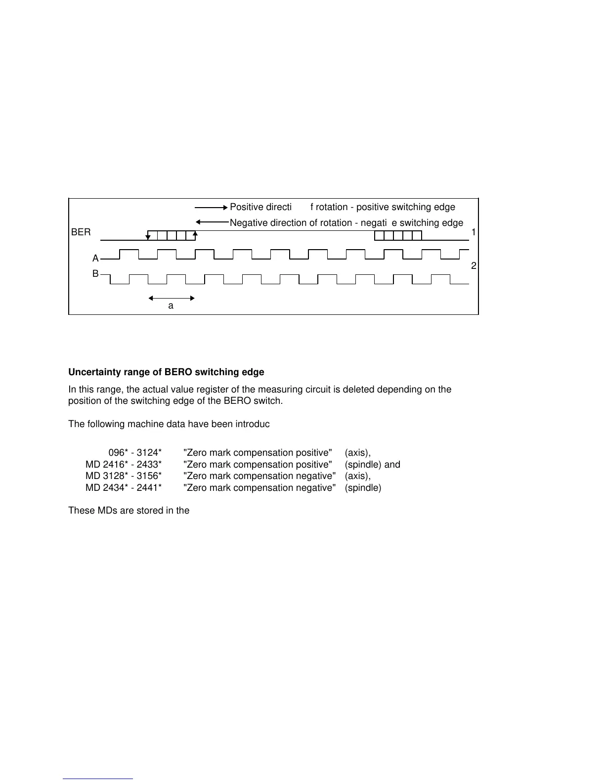
Negative direction of rotation - negative switching edge
a
a
a
a
a
a
a
a
a
a
a
a
a
a
a
a
a
a
a
a
a
a
a
a
a
a
a
a
a
a
a
a
a
a
a
a
a
a
a
a
a
a
a
a
a
a
a
a
a
a
a
a
a
a
a
a
a
a
a
a
a
a
a
a
a
a
a
a
a
a
a
a
a
a
a
a
a
a
a
a
a
a
a
a
a
a
a
a
a
a
a
a
a
a
a
a
a
a
a
a
a
a
a
a
a
a
a
a
a
a
a
a
a
a
a
a
a
a
a
a
a
a
a
a
a
a
a
a
a
a
a
a
a
a
a
a
a
a
a
a
a
a
a
a
a
a
a
a
a
a
a
a
a
a
a
a
a
a
a
a
a
a
a
a
a
a
a
a
a
a
a
a
a
a
a
a
a
a
a
a
a
a
a
a
a
a
a
a
a
a
a
a
a
a
a
a
a
a
a
a
a
a
a
a
a
a
a
a
a
a
a
a
a
a
a
a
a
a
a
a
a
a
a
a
a
a
a
a
a
a
a
a
a
a
a
a
a
a
a
a
a
a
a
a
a
a
a
a
a
a
a
a
a
a
Positive direction of rotation - positive switching edge
Uncertainty range of BERO switching edge
In this range, the actual value register of the measuring circuit is deleted depending on the
position of the switching edge of the BERO switch.
The following machine data have been introduced in order to compensate for a switching
hysteresis:
MD 3096* - 3124* "Zero mark compensation positive" (axis),
MD 2416* - 2433* "Zero mark compensation positive" (spindle) and
MD 3128* - 3156* "Zero mark compensation negative" (axis),
MD 2434* - 2441* "Zero mark compensation negative" (spindle)
These MDs are stored in the ”Speed ratios” parameter set group, which means that they can
be set for each gear ratio (Description of Functions Section).
The control is unable to detect effects of external influences (speed, temperature, etc.) on this
switching hysteresis. Basically, the different parameter sets permit, however, to parameterize
different zero mark offsets.
The existing MDs (also) remain active:
MD 240* "Reference point offset" (axis)
MD 459* "Zero mark offset" (spindle)
The system does not verify whether the external hardware required for the external zero mark
hardware is actually available (BERO and cabling).
10–18
© Siemens AG 1992 All Rights Reserved 6FC5197- AA50
SINUMERIK 840C (IA)