09.95 6 NC Machine Data (NC MD), NC Setting Data (NC SD)
6.5 Spindle-specific MD (spindle data)
6.5 Spindle-specific MD (spindle data)
Measuring system connection
400*
Default value Lower input limit Upper input limit Units
0 0
05031000
15021015 (up to SW 4)
30021015 (as from SW 5)
–
Active on
Power On
The spindles available on the machine can be allocated to the measuring circuit modules in a
flexible way. They are allocated separately according to actual value inputs (MD 400*) and
setpoint outputs (MD 460*).
Simulation axes/spindles are defined if no measuring system is parameterized (measuring loop
and encoder not entered in MD 200*, MD 400*).
The simulation axis/spindle generates partial actual values from the partial setpoints and
therefore travels without following error. (For more detailed description see MD 200*).
Note:
See Section 5, Machine Data Dialog, for the servo loop assignment.
Spindle drift compensation
401*
Default value Lower input limit Upper input limit Units
0
2)
0
3)
–500
–500
500
500
VELO
2)
0.01% of max.
motor speed
3)
Active
at once
The input value must be modified in the appropriate direction until the spindle exhibits identical
actual speeds in both directions of rotation. The value must be adjusted at low speeds, and
can be checked by viewing the appropriate information in the Basic display in the service
display for spindles (spindles with encoder), using a rev counter, or screening the Service
data. In M 19 (spindle positioning), the spindle drift goes directly into the positioning error.
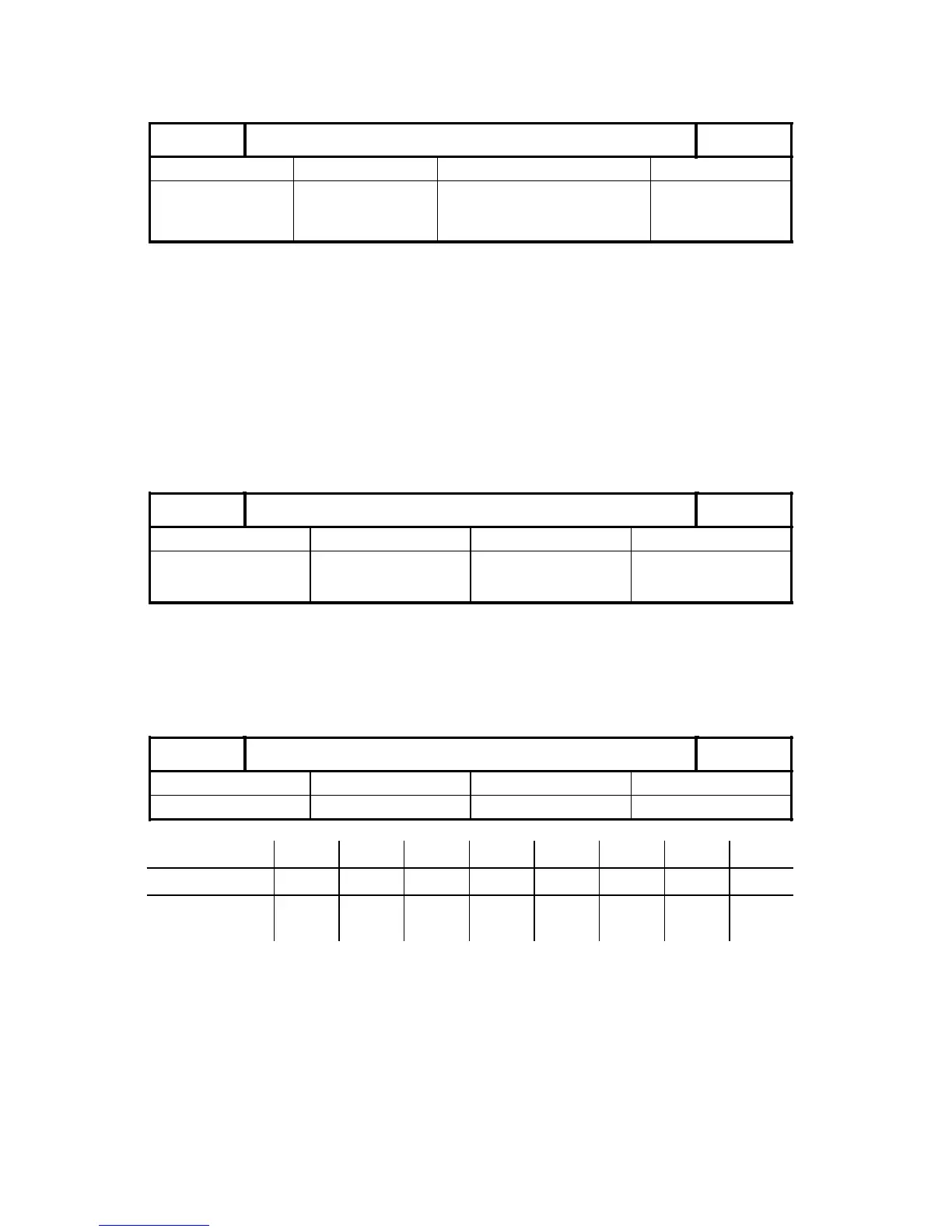
Maximum speed gear stages 1-8
403*-410*
Default value Lower input limit Upper input limit Units
see table +0 99 999 rev/min
1)
Active on
NC Stop
Gear 1 2 3 4 5 6 7 8
NC MD 403* 404* 405* 406* 407* 408* 409* 410*
Default 500 1000 2000
4000
4)
4000 4000 4000 4000 4000
NC MD 403* - 410* specify the maximum spindle speed reached in the individual gears at a
setpoint of 10 V. When no gear is available, the maximum permissible spindle speed is entered
_______
1) The input resolution is 0.1 rev/min, if MD 520* bit 3=1.
2) Up to SW 2
3) As from SW 3
4) As from SW 4
© Siemens AG 1992 All Rights Reserved 6FC5197- AA50 6–65
SINUMERIK 840C (IA)