12.93 12 Functional Descriptions
12.18.16 Examples
12.18.16 Examples
12.18.16.1 Overview of application examples
• Hobbing
• Inclined infeed axes
12.18.16.2 Hobbing
Interrelated functions in hobbing process
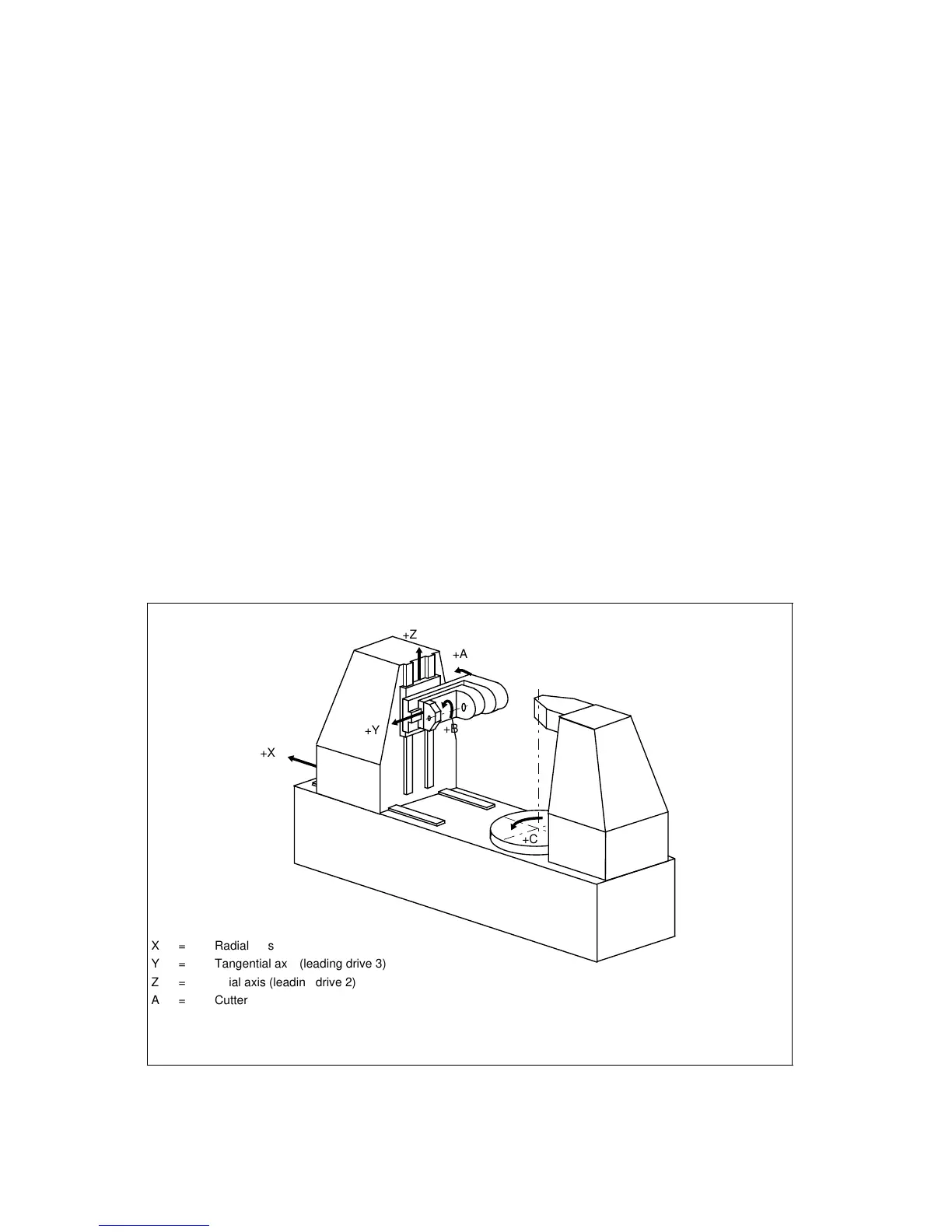
The following diagram shows the configuration of a typical hobbing machine.
The machine comprises five numerically controlled axes and a controlled main spindle.
These are:
• the rotary motion of the workpiece table (C) and hobber (B),
• the axial axis (Z) for producing the feed motion over the entire workpiece width,
• the tangential axis (Y) for shifting the hobber along its axis,
• the radial axis (X) for the infeed of the cutter to tooth depth,
• the cutter swivel axis (A) for setting the hobber in relation to the workpiece depending on
the cutter and tooth lead angles.
The machine can also be equipped with further NC axes to obtain an automatic workpiece and
tool changer.
Definition of axes on a hobbing machine (example)
a
a
a
a
a
a
+Z
+X
a
a
a
a
+Y
a
a
a
a
a
a
+B
a
a
a
a
+C
a
a
a
a
+A
X = Radial axis
Y = Tangential axis (leading drive 3)
Z = Axial axis (leading drive 2)
A = Cutter swivel axis
C = Workpiece rotary axis (following drive)
B = Cutter rotary axis, main spindle (leading drive 1)
© Siemens AG 1992 All Rights Reserved 6FC5197- AA50
12–175
SINUMERIK 840C (IA)