10 Axis and Spindle Installation 09.95
10.4.1 Drive optimization
Example (for analog):
”V
max
” = 300 mm/min MD 256* = 3000 or 6000 with SW 3
”U
max
” = 9000 mV MD 260* = 90000 or 18000 with SW 3
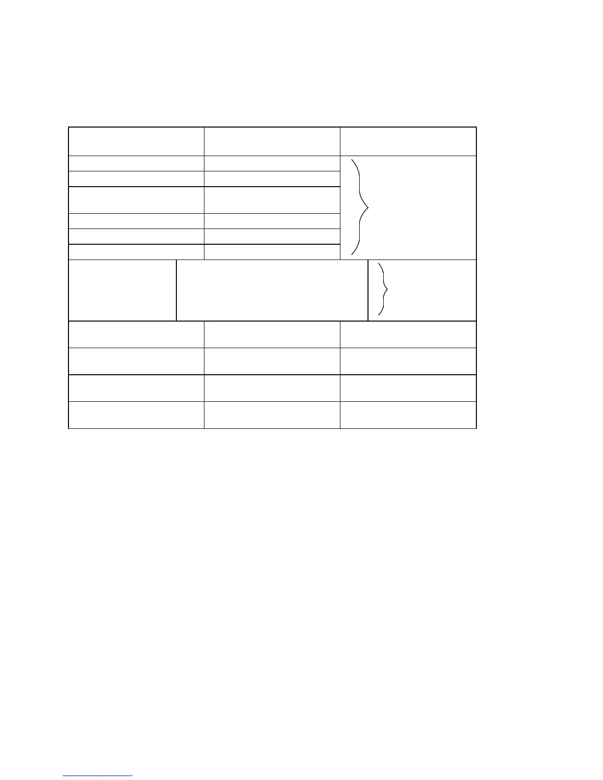
Example of a linear axis
for digitalfor analog
Input/display resolution IS = 10
-4
inch
Position control resolution MS = 0.5 · 10
-3
mm
Rated motor speed
or FDD MD 1400
n = 3000
rev
/
min
Spindle pitch s = 10
mm
/
rev
Gear (spindle motor) r = 1 : 2 = 0.5
Required max. setpoint U = 9.5 V
Max. velocity V
max
[mm] = n · S · r
V
max
[mm] = 3000
rev
/
min
· 10
mm
/
rev
· 0,5
V
max
[mm] = 15000
mm
/
min
V
max
[inch] = 15000
mm
/
min
: 25.4
mm
/
inch
= 590.55
inch
/
min
590
inch
/
min
MD 256*, Scaling factor
maximum velocity
15 000 [
mm
/
min
] 15 000 [
mm
/
min
]
MD 260*, Scaling factor
maximum speed setpoint
9 500 [mV] or [0.01 %] 10 000 [mV] or [0.01 %]
MD 280*, Maximum velocity
(progr. rapid traverse G00)
5 900 [1000 · 10-4
inch/min]
5 900 [1000 · 10
-4
inch
/
min
]
FDD MD 1147 speed
limitation
–– 3 300
as for analog
as for analog
A speed setpoint of 7730 VELOS or 9500 [0.01 %] results in rapid traverse. The converted
value of 9436 or 9500 is entered in MD 260* (for analog only).
Maximum speed setpoint
The maximum value to be output as the speed setpoint is defined with MD 268*, maximum
speed setpoint. If the limit is exceeded, alarm 104*, ”DAC monitor has responded” is triggered.
The internal speed setpoint is also monitored. If the speed setpoint set is too high, alarm 156*,
”Speed setpoint alarm limit activated”, is triggered.
The alarms appear when the tacho compensation (for analog only) has not been carried out
correctly or there is a measuring circuit or drive error.
For axes whose maximum velocity is reached at approx. 9 V, for analog, or 100%, for digital,
the standard values can be used for the machine data.
Matching is necessary when the maximum velocity is reached at a low speed setpoint voltage.
This applies to axes for which the theoretical maximum velocity has to be limited for
mechanical reasons, e.g. pulse encoder.
The tacho compensation must be set to the desired maximum speed setpoint. This speed
setpoint must be entered in MD 268* taking account of the control margin of 5 - 10%. For
MD 264*, a value that is 20% higher than that for MD 268* is selected.
10–22
© Siemens AG 1992 All Rights Reserved 6FC5197- AA50
SINUMERIK 840C (IA)