09.95 10 Axis and Spindle Installation
10.4.1 Drive optimization
Enter the servo gain according to the following conversion formula in NC MD 252*:
K
V
(0.01 s
-1
) =
5000
3
K
V
m/min
mm
·
= 1666 K
V
m/min
mm
·
The numerical value 1666 is thus input for the K
V
factor 1.
To evaluate the starting conditions and determine whether the set maximum value has been
selected correctly, use the dynamically most unfavourable axis that contributes to continuous
path control.
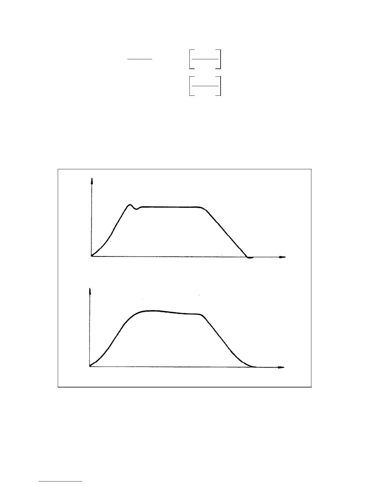
Measure the setpoint voltage n
set
to the speed controller with an oscillomink ink jet plotter,
storage oscilloscope or with the integrated servo start-up function (Section 9). Traverse at
various feedrates.
n
set
[V]
n
set
[V]
t [ms]
t [ms]
Especially deceleration can be observed with high voltage gain on the screen.
© Siemens AG 1992 All Rights Reserved 6FC5197- AA50 10–25
SINUMERIK 840C (IA)