09.01 10 Axis and Spindle Installation
10.4.1 Drive optimization
Example:
Maximum jerk (r): 50 m/s
3
Maximum acceleration (a): 4 m/s
2
Programmed velocity (v) 24 m/min
Interpolation cycle (TIPO): 10 ms
A jerk of 50 m/s3 results in a change in acceleration per IPO cycle of 0.5 ms/2.
This is calculated as follows:
100·TIPO·s
2
r=50 =
m
s
3
/TIPO
50 m
= 0.5
m
s
2
With jerk limitation the maximum acceleration of 4 m/s2 is not reached until 8 IPO cycles have
elapsed.
In addition, the change in acceleration of 0.5 m/s2 per IPO cycle results in a change of velocity
of 0.005 m/s (corresponds to 0.3 m/min) per IPO cycle.
This is calculated as follows:
a=0.5
=
0.5 m
100·TIPO·s
= 0.005
m
min
m
s
2
/TIPO
m
s
/
TIPO=0.3
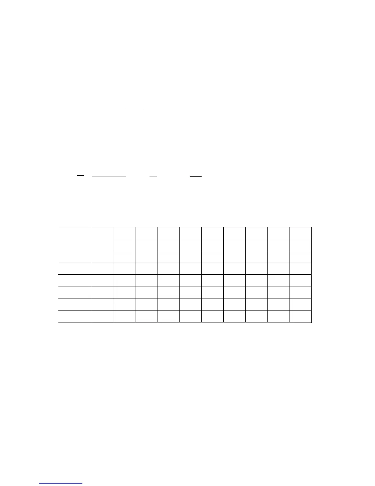
In the table below a movement from zero speed is assumed:
Constant, maximum acceleration takes place In the 8th to 10th IPO cycle. Then, the
acceleration is reduced to zero again with jerk limitation. After 17 IPO cycles a velocity of 24
m/min is reached and a ”constant travel phase” follows.
Time [ms] 10 20 30 40 50 60 70 80 90 100
r [m/s
3
] 0.5 0.5 0.5 0.5 0.5 0.5 0.5 0.5 0 0
a [m/s
2
] 0.5 1.0 1.5 2.0 2.5 3.0 3.5 4.0 4.0 4.0
v [m/min] 0.3 0.9 1.8 3.0 4.5 6.3 84 10.8 13.2 15.6
Time [ms] 110 120 130 140 150 160 170 180 190 200
r [m/s
3
] -0.5 -0.5 -0.5 -0.5 -0.5 -0.5 -0.5 -0.5 0 0
a [m/s
2
] 3.5 3.0 2.5 2.0 1.5 1.0 0.5 0 0 0
v [m/min] 17.7 19.5 21.0 22.2 23.1 23.7 24.0 24.0 24.0 24.0
© Siemens AG 1992 All Rights Reserved 6FC5197- AA50
10–29
SINUMERIK 840C (IA)