06.93 12 Functional Descriptions
12.1.2 Functional description
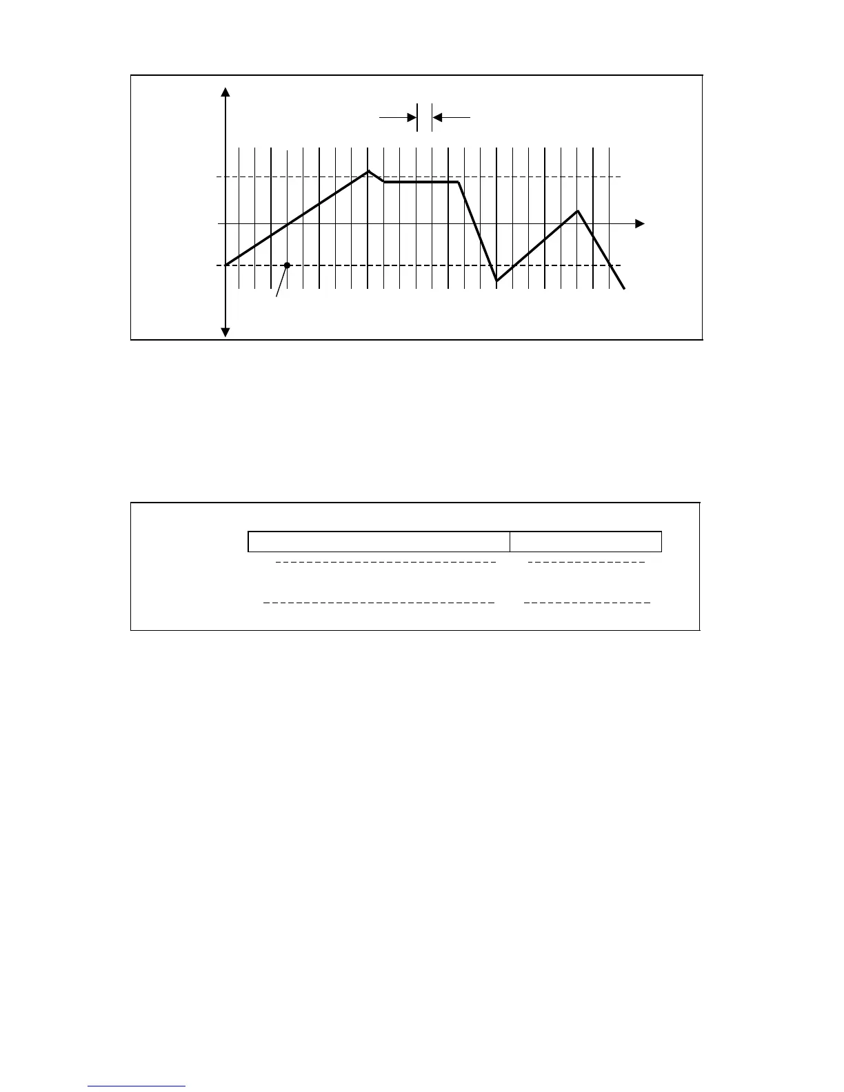
Traverse
path
Spacing
Error=0
Pos.
error
Reference point
Neg.
error
It is then specified how many compensating points must be supplied by means of the entered
spacing between 2 leadscrew error compensation points and the end stops at the machine.
Since leadscrew error compensation is only active when the axis is synchronized - at the
reference point - particular significance is attached to the compensation point coinciding with
the reference point. This compensation point is entered in encoded form in MD 316*. The
compensating value at this point must be 0.
MD 316 * 0 198 249
6249
6198
1000
793
6000
1
Compensation point
NC MD
In view of the fact that the SINUMERIK 840C has a total of 1000 compensation points for all
axes, the control must be informed via MD 316* as to which of these 1000 points corresponds
to the axis reference point. The compensation point is not entered directly in MD 316*, the MD
offset (MD 6125 = MD offset = 125) being entered instead, so the reference point can only
be located on compensation points 1, 5, 9, 13, 17, ... .
© Siemens AG 1992 All Rights Reserved 6FC5197- AA50 12–5
SINUMERIK 840C (IA)