12 Functional Descriptions 11.92
12.1.2 Functional description
K17
+
K5
K16
K20 K24
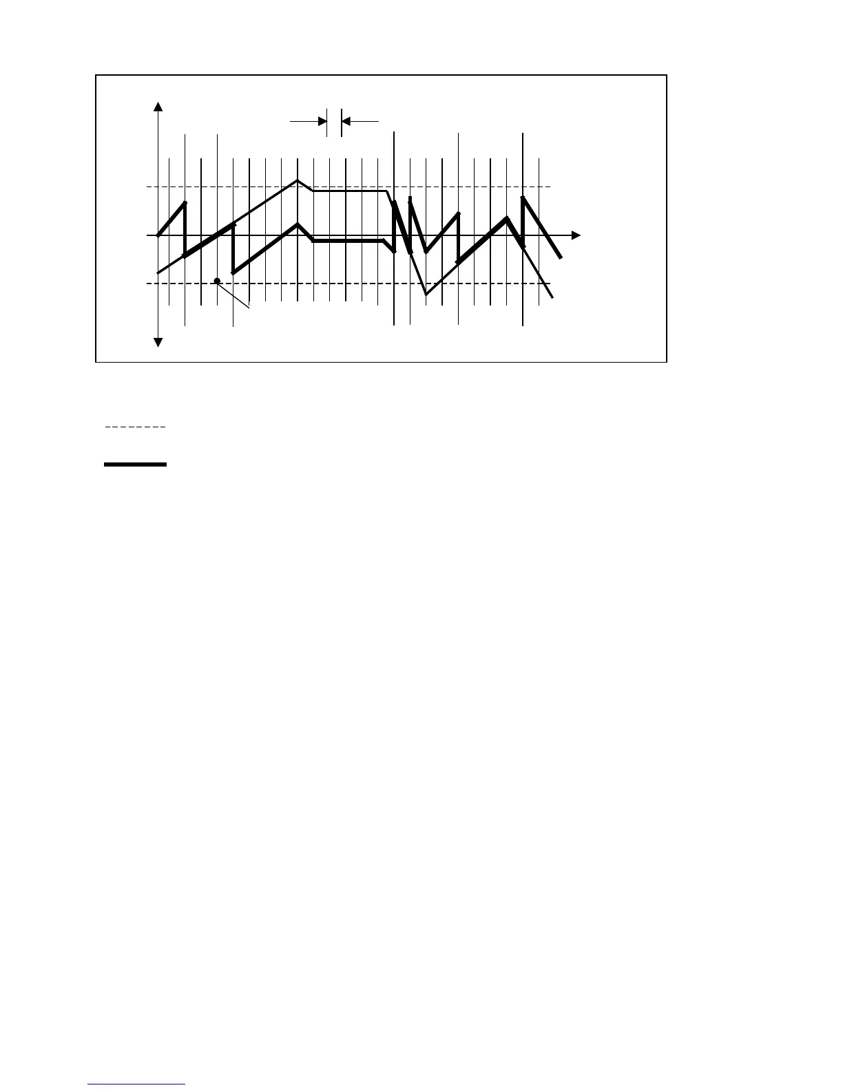
Traverse path
Error
= 0
Pos.
error
Neg.
error
–
+ +
K3
K6
–
+
Reference point
Spacing
Tolerance band e.g. 10 µm
Compensated curve
Compensation value e.g. 5 µm
Commencing at the reference point and proceeding in a negative direction, the error curve
runs to the end of the traverse path within the tolerance band. No compensation is necessary.
A better result is obtained through positive compensation at K3. To stick as closely as possible
to 0 error, compensation in a positive direction of travel must be negative at K6, positive at
K16 and K17, negative at K20, and positive again at K24.
The following machine data must be set:
• Option leadscrew errror compensation
• NC MD 3161 = 1 (to define K5 as reference point)
• NC MD 3241 = 10000 (10 mm spacing)
• NC MD 3281 = 5 (compensation value 5 µm for position control resolution of
1/2 x 10
-3
mm)
• NC MD 6000 = 00 11 00 00 (positive compensation at K3)
• NC MD 6001 = 00 00 10 00 (negative compensation at K6; bits 0 and 1 must be 0)
• NC MD 6002 = 0 no compensation
• NC MD 6003 = 0 no compensation
• NC MD 6004 = 00 00 11 11 ( positive compensation at K16 and K17)
• NC MD 6005 = 00 00 10 00 (negative compensation at K20)
• NC MD 6006 = 00 00 11 00 ( positive compensation at K24)
12–8
© Siemens AG 1992 All Rights Reserved 6FC5197- AA50
SINUMERIK 840C (IA)