11.92 12 Functional Descriptions
12.7.2 Description of the spindle modes
Example for case 1a
a
a
a
a
a
a
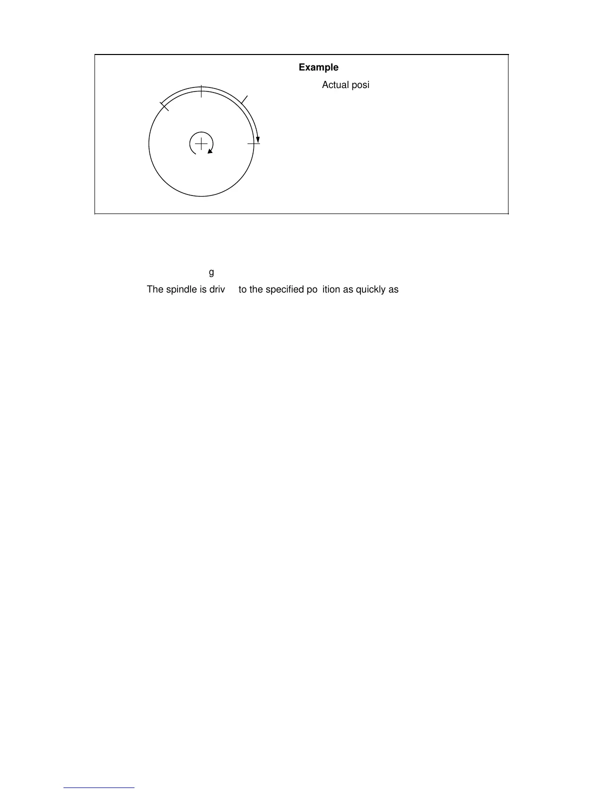
Example
Actual position: 315°
Programmed position: 90°
Shortest path: +135°
a
a
a
a
a
a
0°
a
a
a
a
a
a
a
a
a
a
a
a
b) Spindle running
The spindle is driven to the specified position as quickly as possible, without
changing the direction of rotation.
The nearest position at which the spindle can be stopped is calculated from the
actual position and the deceleration distance based on the momentary speed. The
spindle is driven to the specified position in the direction of travel. The sum of this
required distance and the deceleration distance then gives the distance to be
traversed, which is covered as quickly as possible.
If the actual speed is less than the creep speed, the spindle is accelerated up to
and no further than the creep speed.
If the actual speed is greater than the creep speed, the spindle decelerated until
the creep speed has been reached (MD 427*). Then the M19 position is
approached with interpolation until the spindle can be stopped at the specified
position utilizing maximum deceleration.
© Siemens AG 1992 All Rights Reserved 6FC5197- AA50 12–41
SINUMERIK 840C (IA)