∅° = sin
-1
(VOS / V
phase
) Where: VOS = Velocity of sound in liquid
V
phase
= Phase velocity of sensor
T
L
= 2 * ID / (VOS * cos
∅) ID = Pipe inside diameter
T
L
= Transit time in liquid
V
F
= V
phase
* DT / (2 * TL) DT = Measured Transit-Time difference
V
F
= Flow Velocity
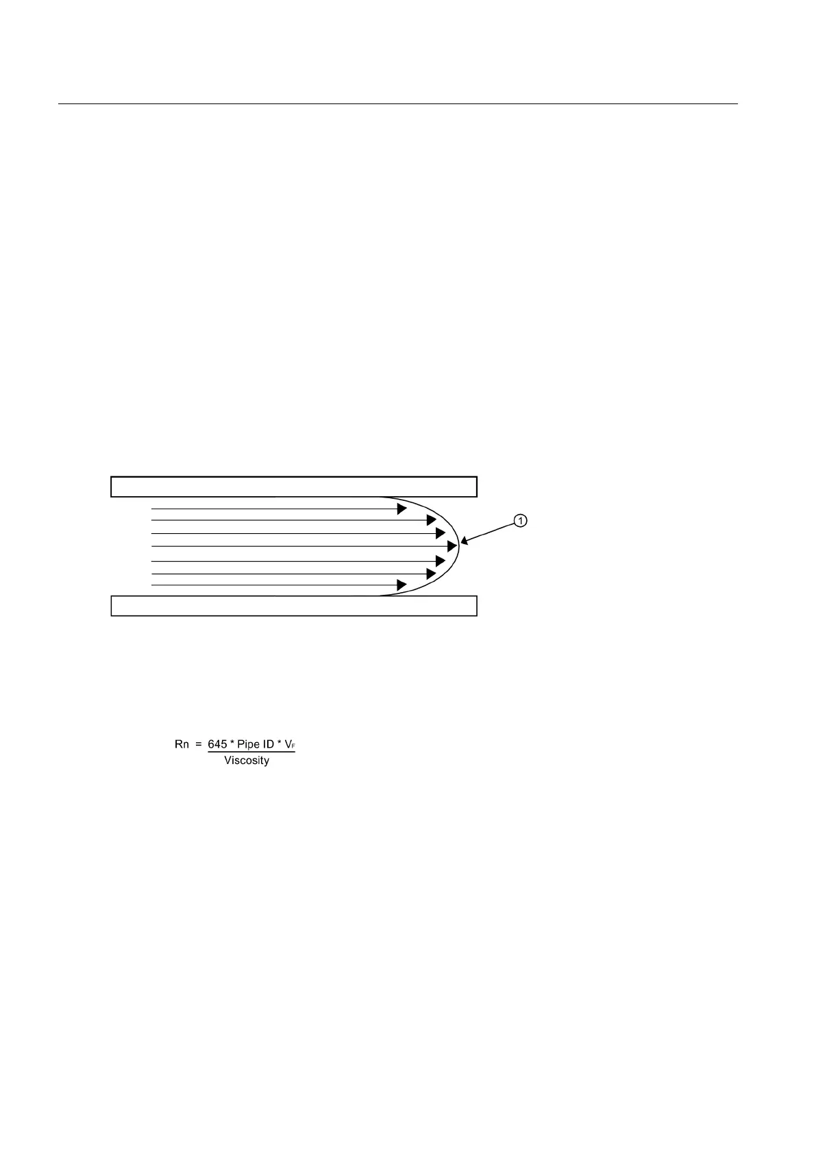
Flow Profile Compensation
Another important consideration is that the ultrasonic flowmeter has to compensate for the
flow profile to maintain calibration accuracy. Shown below is a graphic of a "fully-developed"
flow profile. Note that the fluid velocity increases toward the center (axis) of the flow stream.
① Fluid velocity near the axis of the flow stream tends to be greater.
The Reynolds number is then computed as follows:
where viscosity = cS = cP/density
cS = kinematic viscosity
cP = absolute viscosity
The flowmeter then uses this computation of Reynolds number to compensate the raw flow
velocity for conditions of laminar or turbulent flow profile as defined by an internal Reynolds
compensation table. The flowmeter then
converts the compensated flow velocity to volumetric
flow rate.
Rate = V
F
* Comp(Rn) * Pipe area
Description
3.3 Theory of Operation
FUP1010 IP67 Portable Flowmeter
14
Operating Instructions, 02/2010, A5E02951522A Revision 01

 Loading...


