Home
Siemens
Measuring Instruments
SITRANS FUP1010
Siemens SITRANS FUP1010 User Manual
4
of 1
of 1 rating
208 pages
Give review
Manual
Specs
To Next Page
To Next Page
To Previous Page
To Previous Page
Loading...
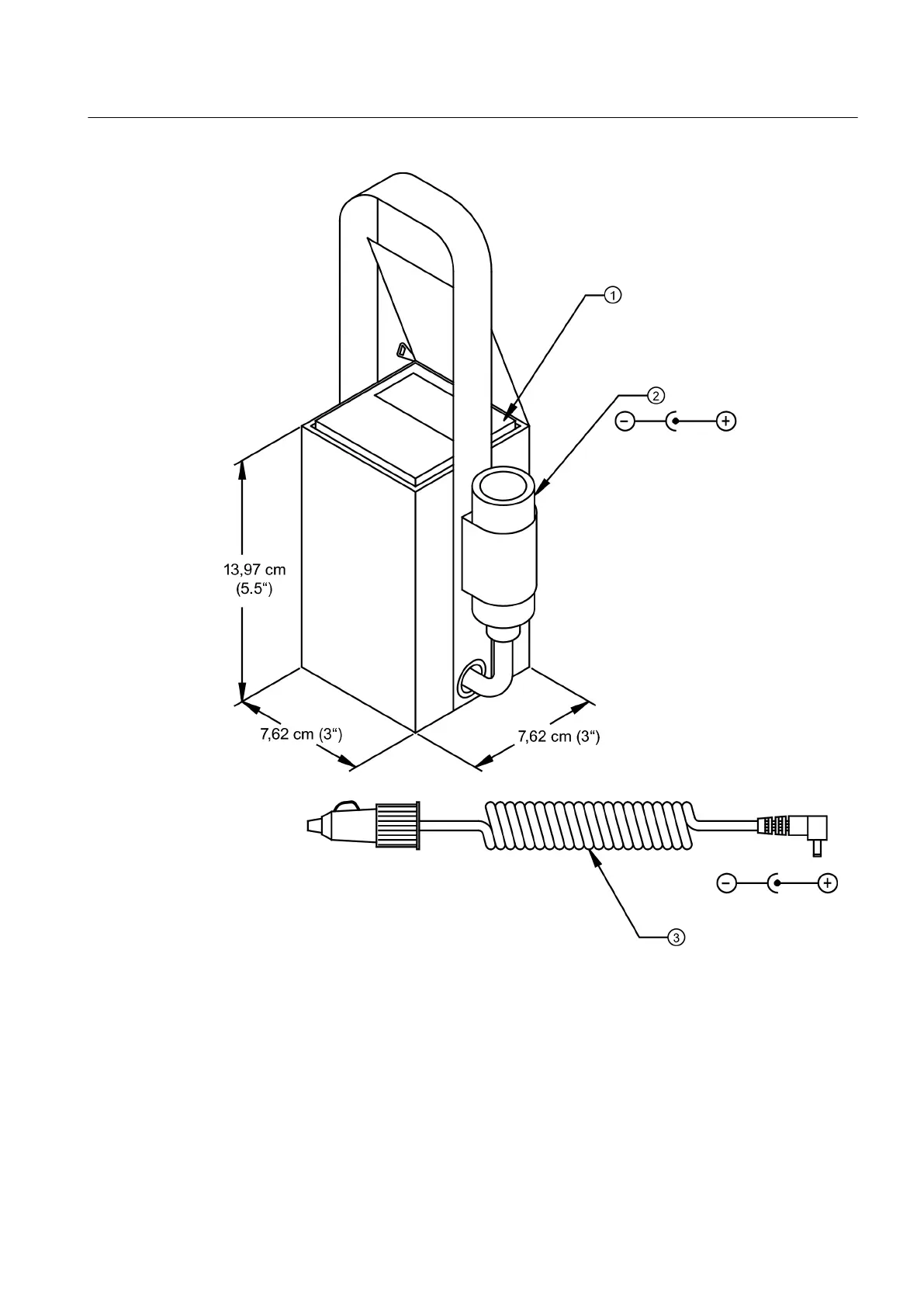
①
Battery Lead Acid Gel (12VDC, 3 AH)
②
Female "Cigarette" Connector
③
Adapter Cable 1.22 meters Extended (4 ft)
Figure 5-1
External Battery Pack
Charging the External Battery Pack
Connecting
5.1 Transmitter Wiring
FUP1010 IP67 Portable Flowmeter
Operating Instructions, 02/2010, A5E02951522A Revision 01
25
26
28
Table of Contents
Default Chapter
5
Table of Contents
5
1 Introduction
9
Preface
9
Items Supplied
9
History
9
Connecting
9
Further Information
10
2 Safety Notes
11
Laws and Directives
11
Lithium Batteries
12
3 Description
13
FUP1010 Features
13
Figure 3-1 Weatherproof Case-Shown Open
13
Commissioning
13
Applications
14
Functions
14
Theory of Operation
15
4 Installing/Mounting
21
Installation Safety Precautions
21
Use According to Specifications
21
Application Guidelines
22
Charging the Battery
22
Table 4-1 Power Cord Codes
23
Figure 4-1 Power Adapter/Battery Charger
23
5 Connecting
25
Transmitter Wiring
25
Connecting Battery Power
25
Maintenance and Service
25
Figure 5-1 External Battery Pack
27
Figure 5-2 1015BCK-2 and 1015BCA-2 Battery Chargers
29
Connecting AC Power
30
Sensor Wiring
30
Preliminary Installation Procedures
30
Figure 5-3 Power Adapter/Ac-Charger for Dual Channel Flowmeter
30
Figure 5-4 Reflect Mount (Pipe Shown from above in 12 O'clock Position)
31
Figure 5-5 Direct Mount (Pipe Shown from above in 12 O'clock Position)
32
Figure 5-6 Sensor Alignment (Horizontal Plane)
33
Sensor Identification and Selection
34
Setting the Parameters
35
Table 5-1 Pipe Configuration Option List Definitions
38
Reflect Mount
39
Figure 5-9 Sensor Mounting with E-Z Clamp and Spacer Bar
41
Figure 5-11 Sensor
42
Direct Mount
43
Figure 5-14 EZ Clamping Sensor to Pipe
45
Figure 5-17 Wrapping the Mylar Spacing Guide Around the Pipe (End View)
48
Figure 5-19 Aligning the Sensors for Direct Mode (End View)
49
1012T Mounting Tracks
50
Figure 5-21 Reflect Mount with Model 1012TP Mounting Track (Side View)
52
Figure 5-22 Reflect Mode Chain Loop (Front View)
53
Figure 5-23 Direct Mount 180° Opposed with Mounting Tracks
56
Figure 5-24 Direct Mount Roller Chain
58
Figure 5-25 Wrapping the Mylar Spacing Guide Around Pipe (End View)
59
Figure 5-27 Track Rail Alignment
60
Figure 5-28 REF and Number Index Pin Locations
61
Zero Flow Adjust Menu
62
6 Commissioning
67
General Requirements
67
Navigating the Menu
68
Table 6-1 Key Pad Function Chart
69
Installation Menus
70
7 Functions
75
Selecting Flow Units
75
Table 7-1 Totalizer Modes
76
Table 7-2 Totalizer Controls (the "N" in <Fn> = Channel Number)
77
Span Data
78
Logger Control
80
Table 7-3 Logger Control Menu Option List
80
Operation Adjust Menu Settings
83
Setting Relays
86
Table 7-4 Relay Option List
86
Memory Control
88
Table 7-5 Memory Control Menu
88
Analog Output Setup
89
Table 7-6 Analog Outputs
89
Table 7-7 Analog out Setup Data Categories
89
Analog Input Setup
91
Analog Output Trim
93
Table 7-8 Analog out Trim Menu Structure
93
RTD Calibration
96
Table 7-9 RTD Calibrate Menu Structure
97
Reflexor
98
Figure 7-2 Adjacent Sensor Mounting
101
Table 7-10 Inline Metal and Plastic Pipe Cable Connections
101
Figure 7-4 Spectra Graph Display Screen
106
Table 7-11 Cursor Definitions
107
Table 7-12 Diagnosic Data
109
8 Alarm, Error, and System Messages
111
Alarm Letter Codes and Descriptions
111
Table 8-1 Alarm Codes and Descriptions
111
9 Maintenance and Service
113
Maintenance
113
Replacing the Battery
113
Figure 9-1 Faceplate Removal
114
Figure 9-2 Battery Cover Removal
115
Battery Disposal
116
Technical Support
116
Return Procedures
117
10 Troubleshooting
119
Table 10-1 Troubleshooting Tips
119
F4 Reset Procedure
120
Test Facilities Graph Screen
121
Figure 10-2 Setting Digital Damping Factor
125
Figure 10-3 Setting the Mindamp Factor
126
Table 10-2 Description of Graph Screen Text Display Parameters
129
Table 10-3 Hot Key Summary
129
Site Setup Data
130
Table 10-4 Site Setup Menu Items
131
11 Technical Data
137
Table 11-1 Performance Specifications
137
Appendix
139
Certificates
139
Accessories and Spare Parts
139
I/O Connections and Wiring
139
Table A-1 Part Numbers and Connection Data
139
Table A-2 2 Channel/2 Path Input/Output Terminal Block Wiring
139
A.1 Certificates
139
Site Setup for SITRANS F
140
Flowrate Calibration and Calibration Tables
147
Appendix
151
Installation/Outline Drawings
151
B.1 Installation/Outline Drawings
151
Glossary
153
Index
205
Other manuals for Siemens SITRANS FUP1010
Quick Start
46 pages
4
Based on 1 rating
Ask a question
Give review
Questions and Answers:
Need help?
Do you have a question about the Siemens SITRANS FUP1010 and is the answer not in the manual?
Ask a question
Siemens SITRANS FUP1010 Specifications
General
Brand
Siemens
Model
SITRANS FUP1010
Category
Measuring Instruments
Language
English
Related product manuals
Siemens SITRANS FUE380
118 pages
Siemens SITRANS FUS080
95 pages
Siemens SITRANS FUS380
118 pages
SITRANS FUE1010 IP65 NEMA 4X
296 pages
SITRANS FUG1010 IP65 NEMA 4X
268 pages
Siemens SITRANS F
306 pages
Siemens SITRANS F M
24 pages
Siemens SITRANS FX300
80 pages
Siemens SITRANS FX330
124 pages
Siemens SITRANS FMS500
68 pages
Siemens Sitrans F Series
356 pages
Siemens SITRANS F M MAG 5000
107 pages