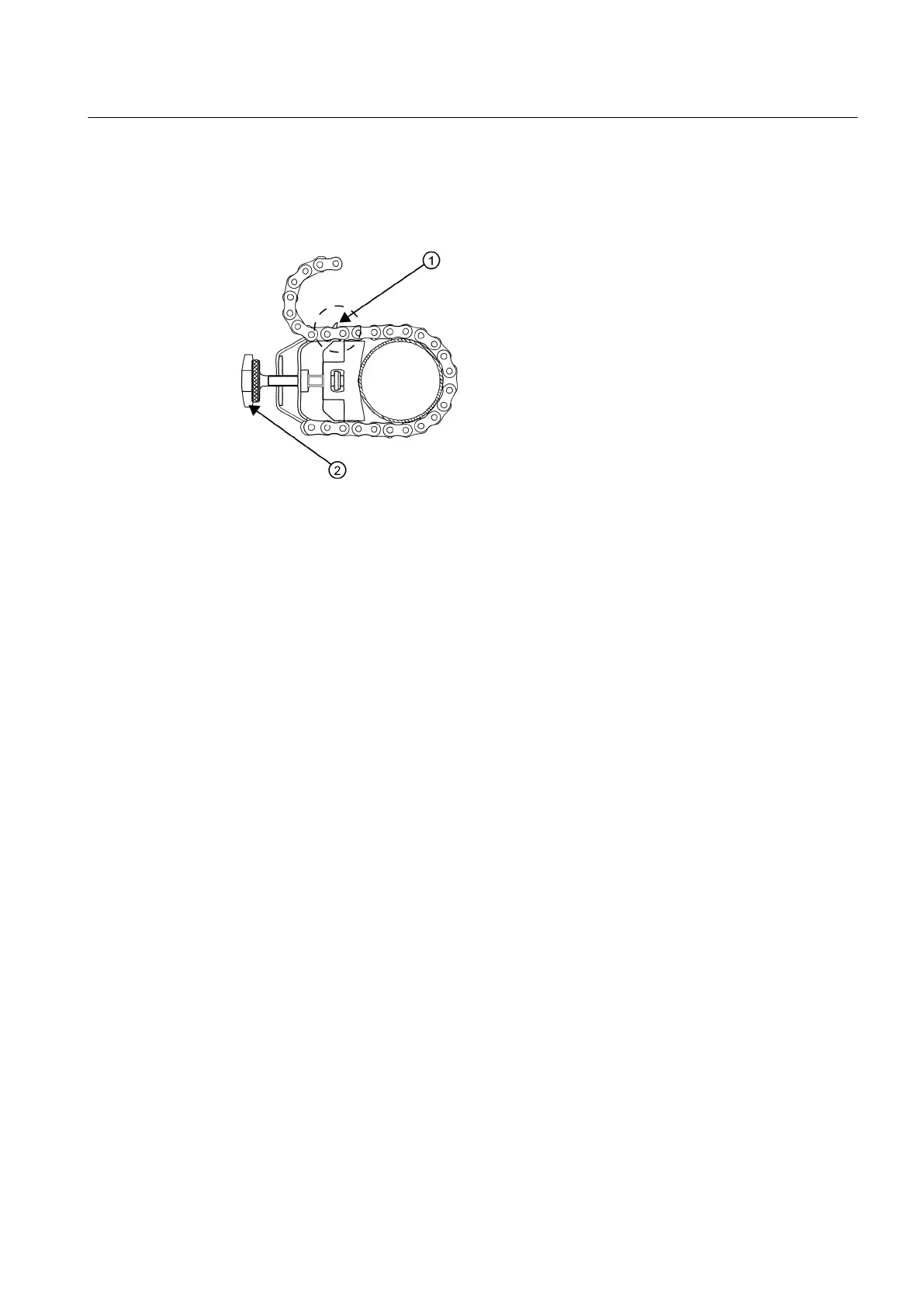
4. Holding the track assembly in place, loop one of the roller chains under the pipe, pull it
around and maintain
tension while slipping a link over the tension screw hook. Tighten the
tension screw enough to hold the assembly on the pipe, but still allow rotation. Repeat for
the other roller chain.
① Loop chain over tension screw hook
② Chain tension screw
Figure 5-22 Reflect Mode Chain Loop (Front View)
5. Rotate the track rail assembly to the intended mounting position on the pipe, then tighten
both tension screws just enough to prevent rotation. Do not over tighten.
6. With pencil or chalk, mark a generous area around the perimeter of the track assembly.
Loosen and move the track assembly away from the marked area.
7.
Prepare the area you marked by degreasing the surface, if needed, and removing any grit,
corrosion, rust, loose paint or surface irregularities with the abrasive pipe conditioning
material provided. Clean the pipe of all debris and abrasive particles.
8. Rotate the track into the position that was just cleaned. Insert the index pin into the REF
hole.
9. Select a sensor and apply a thin band of couplant compound to the sensor’s emitting
surface.
10.Place the sensor between the track rails, slightly behind the pin and under the clamping
screw assembly. Slide it forward until it butts up firmly against the reference pin.
11.Once the sensor is in place secure it with the sensor clamping screw. Do not over tighten.
12.Repeat procedure for Number Index sensor making sure to insert an index pin into the
correct Number Index hole. Refer to the Model 1012TP Mounting Track (side view) figure
above.
13.Observing the upstream and downstream orientation, attach the UP and DN cables to the
sensors and make snug. Attach the other ends to the UP and DN terminals of the flowmeter.
Installing a 1012T Mounting Track in Direct Mode
The Sensor Installation procedures show how the automatic selection of sensors, mounting
mode and spacing method are established. Examine the figure below, which illustrates a typical
Connecting
5.2 Sensor Wiring
FUP1010 IP67 Portable Flowmeter
Operating Instructions, 02/2010, A5E02951522A Revision 01
51

 Loading...


