Sensor Installation
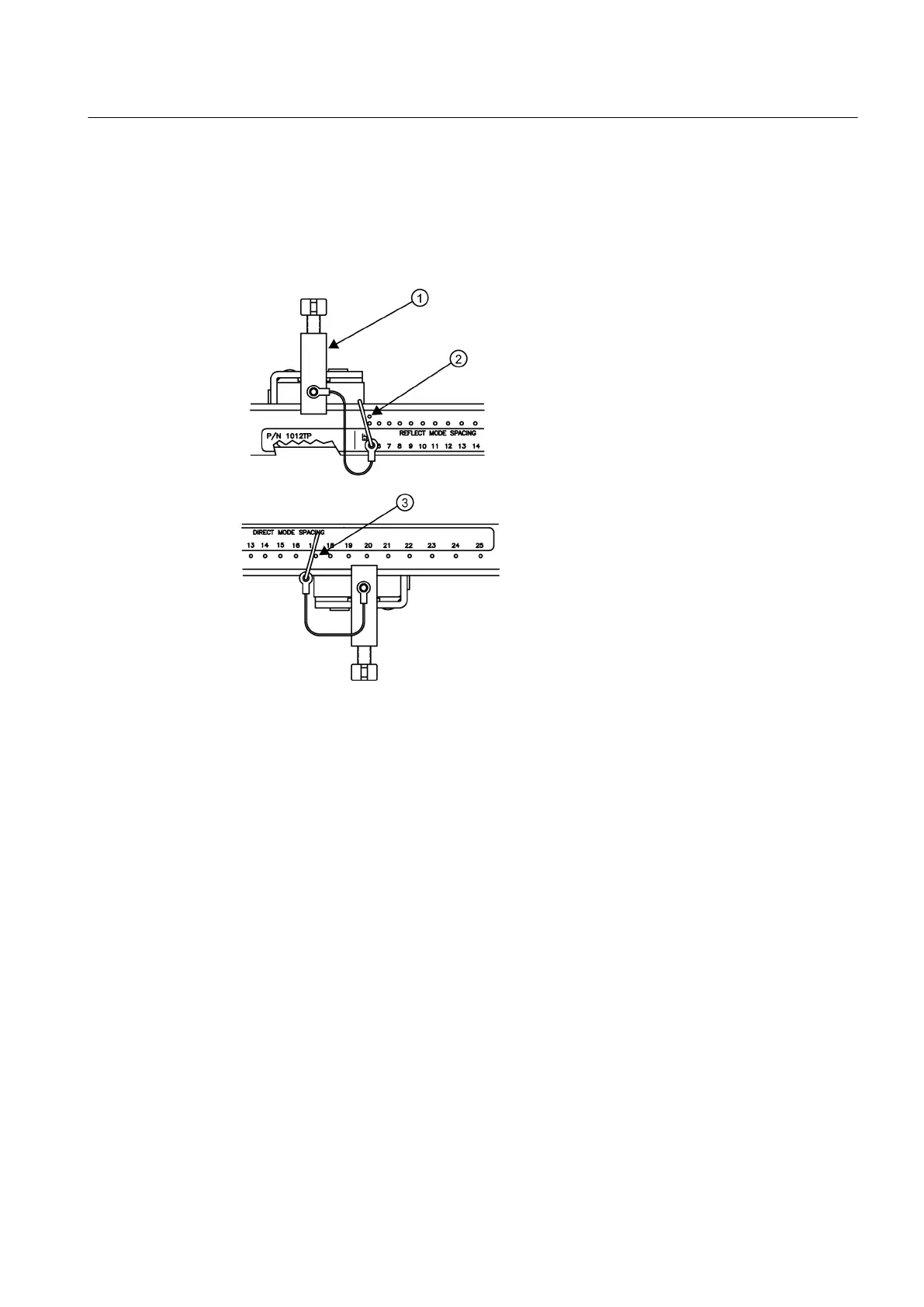
1. Insert an index pin into the REF hole of the track marked "Reflect Mode Spacing."
2. Take
one of the sensors and insert it between the track rails and to the left of the index pin
with the cable connector pointing away from the pin. Move the sensor until the pin stops it.
Hold sensor in place. Move sensor clamping screw over the sensor and tighten.
① Sensor Clamping Screw
② REF hole
③ Number Index hole
Figure 5-28 REF and Number Index Pin Locations
3. Insert the other index pin into the correct Number Index hole on the other track marked
"Direct Mode Spacing."
4. Insert the second sensor into the track rail with its cable connector pointing away from the
pin. Move the sensor until it’s stopped by the pin. Move sensor clamping screw over the
sensor and tighten.
5. Using a pencil or chalk, mark a generous area around where the sensors contact the pipe.
6. Release the tension on the sensors and remove them.
7. Loosen the chains and rotate the track assembly on the pipe so you can gain access to the
areas marked.
8. Prepare the areas you marked by degreasing the surface, if needed, and removing any
grit, corrosion, rust, loose paint or surface irregularities with the abrasive pipe conditioning
material provided.
9. Rotate the track assemblies into their original position on the pipe. Use the edge of the
Mylar guide as a stop for both tracks and keep them parallel. Align each track with the
"center line" you previously marked on the Spacing Guide. Tighten tracks securely.
Connecting
5.2 Sensor Wiring
FUP1010 IP67 Portable Flowmeter
Operating Instructions, 02/2010, A5E02951522A Revision 01
59

 Loading...


