16.Wrap the Mylar spacing guide around the pipe so that the left edge is against the sensor
edge mark (see "C" above). Arrange so that one end overlaps the other by at least 8 cm
(3 inches). Trim
to fit if necessary, but in order to keep the end square, be sure not to trim
at the overlapping end.
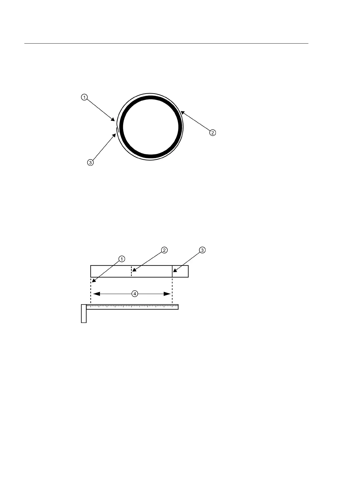
① Trim material from inner edge if necessary
② Mylar Spacing Guide
③ 8 cm (3-inches) Overlapping Edge
Figure 5-17 Wrapping the Mylar Spacing Guide around the pipe (End View)
17.Realign left edge of the guide with the sensor edge mark. Line up both vertical edges of
the guide and, ensuring that it is snug around the pipe, mark along the overlapping edge.
18.Remove Mylar spacing guide and lay it out on a flat surface. Either measure the exact
distance
half-way between the overlap edge and the mark at the overlap, or fold the guide
from the overlap edge to the overlap mark and draw a line at the fold (halfway point).
① Overlap Edge ③ Mark on Spacing Guide
② Mark (or fold) exactly at half-way point ④ Circumference
Figure 5-18 Finding the Halfway Distance
19.Reinstall the spacing guide; its left edge abutting the sensor's edge mark on the pipe and
the overlapping
edge in line with the dot (now a line) on the pipe (see "C above). Tape it in
this position on the pipe. Take the second frame and place it against the edge of the guide
with its tapered roller centered on the center mark on the guide.
Connecting
5.2 Sensor Wiring
FUP1010 IP67 Portable Flowmeter
46
Operating Instructions, 02/2010, A5E02951522A Revision 01

 Loading...


