20.Temporarily position the sensor (in the 3 o’clock position opposite the mounted sensor -
see below) where it will be mounted. Ensure that this is a smooth area without any raised
spots (seams, etc.). With a pencil or chalk, mark a generous area around all sides of the
mounting frames. Remove the frame and the Mylar guide.
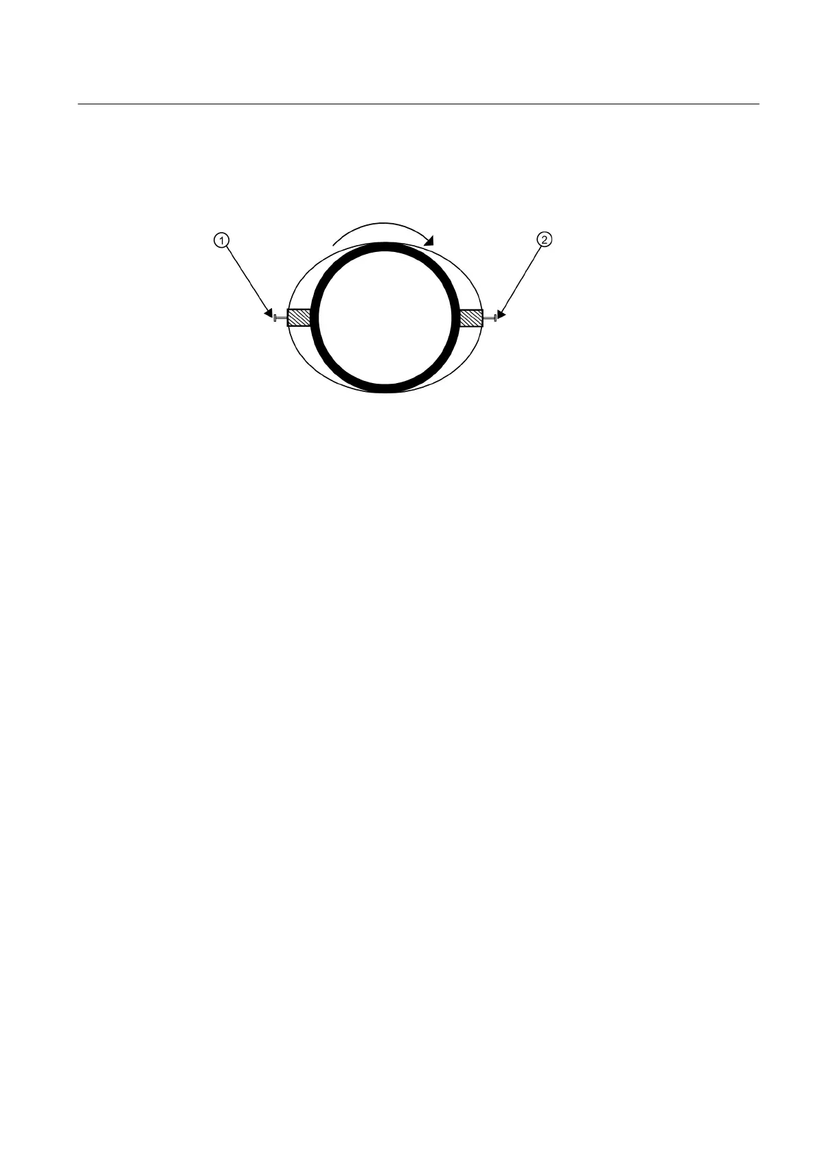
① 9 o'clock Sensor
② 3 o'clock Sensor
Figure 5-19 Aligning the Sensors for Direct Mode (End View)
21.Prepare the area
you marked by de-greasing the surface, if needed, and removing any grit,
corrosion, rust, loose paint or surface irregularities with the abrasive pipe conditioning
material provided. Clean the pipe of any debris and abrasive particles.
22.Replace the Mylar spacer guide back in the same position it was in and retape it to the pipe.
23.Attached the EZ Clamp to the sensor under the spring clip. Unscrew the knob until it's at
the stop.
24.Apply a continuous lengthwise 3mm (1/8-inch) bead of coupling compound across the
center of the sensor emitting surface.
25.Hold the sensor in place and bring chain around pipe and attach to the closest link on the
EZ Clamp "S" hook.
26.Tighten the adjusting nut until the chain is just snug around the pipe. Ensure that the chain
is straight around the pipe and the sensor contacts the pipe at the white dot just under the
front label. Ensure that there is equal space on either side of the dot between the edges of
the sensor and pipe. Adjust if necessary.
27.Tighten chain and ensure that the sensor does not move while tightening. Do not over
tighten.
Connecting
5.2 Sensor Wiring
FUP1010 IP67 Portable Flowmeter
Operating Instructions, 02/2010, A5E02951522A Revision 01
47

 Loading...


