4. One sensor is attached using the "REF" hole on the spacer bar. The second sensor is
attached to the spacer bar at the index hole specified by the Number Index recorded in
Step 1.
Note
In some cases, the sensors may have two sets of securing holes. When using the EZ
Clamp assembly, use the lower set of holes when attaching the spacer bar.
5. Temporarily position the assembly (in the 10 o’clock position) at the location where it will
be mounted. Ensure
that this is a smooth area of the pipe without any raised spots (seams,
etc.).
6. With a pencil or chalk mark a generous area around each sensor where they contact the
pipe. Remove the assembly.
7. Prepare the two areas you marked by degreasing the pipe surface. Remove any grit,
corrosion, rust, loose paint or surface irregularities with the abrasive pipe conditioning
material provided.
8. Remove the sensor from the spacer bar that was attached through the REF hole. Attach
the EZ clamp to the sensor under the spring clip. The adjusting nut knob should be pointing
up and on the side opposite the spacer bar. Unscrew the knob until it’s at the stop.
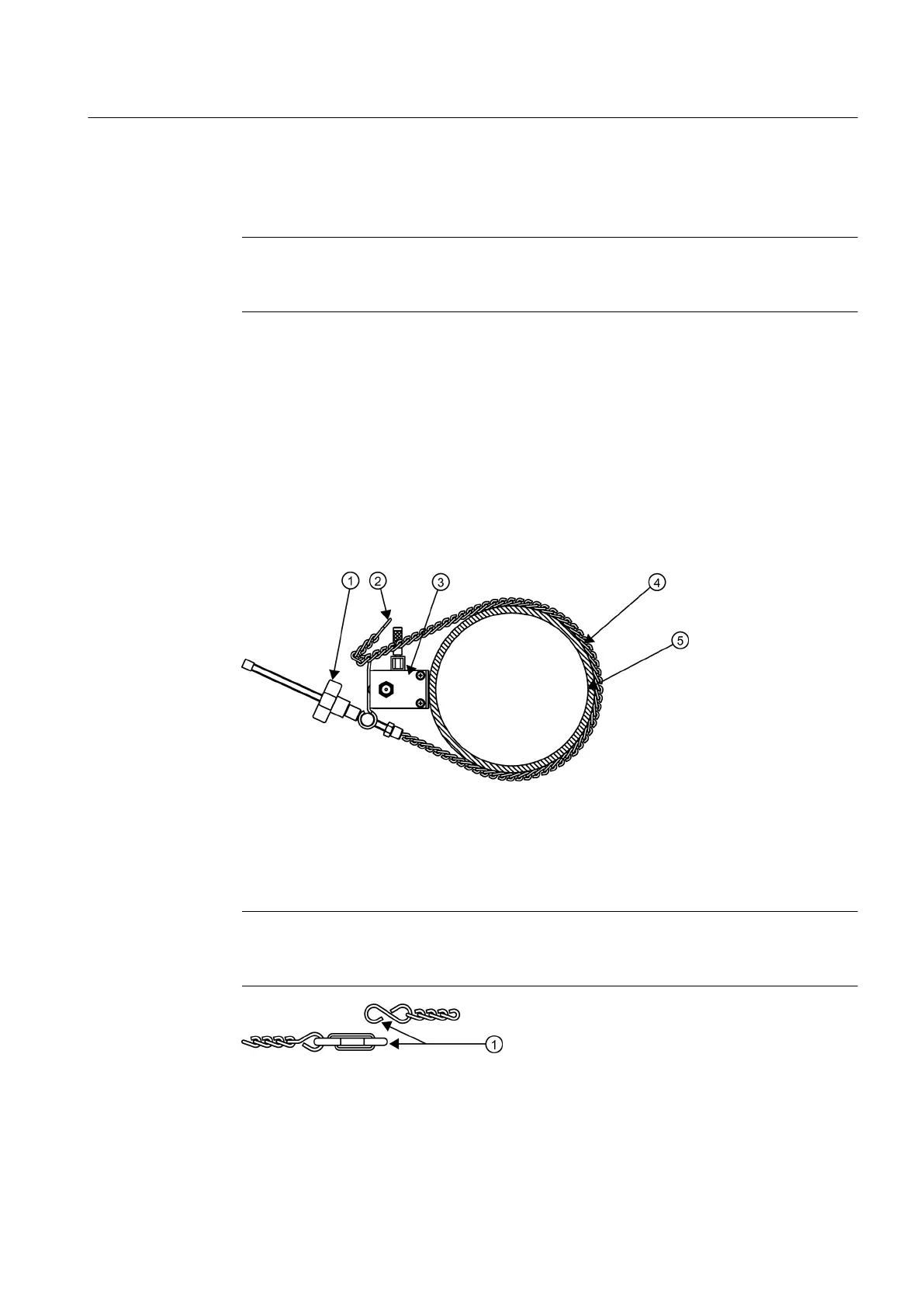
① Adjusting Nut ④ Sensor
② Bit Snap ⑤ E-Z Clamp Chain
③ Spacer Bar ⑥ Pipe
Figure 5-9 Sensor Mounting with E-Z Clamp and Spacer Bar
Note
To surround larger pipes, link multiple lengths of chain together by mating the Bit Snap
and "S" hook.
① Mate Bit Snap and "S" Hook to extend chain
Figure 5-10 E-Z Clamp S-Hook
Connecting
5.2 Sensor Wiring
FUP1010 IP67 Portable Flowmeter
Operating Instructions, 02/2010, A5E02951522A Revision 01
39

 Loading...


