28.Observing the upstream
and downstream orientation, attach the UP and DN cables to the
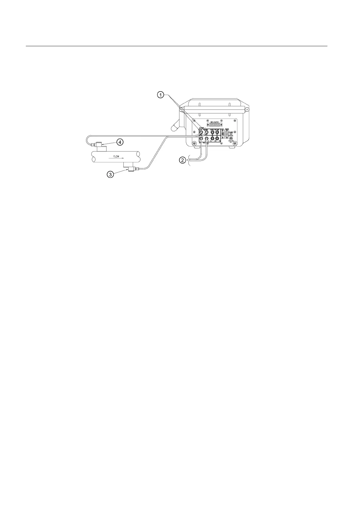
sensors and make snug. Attach the other ends to the UP and DN terminals of the flowmeter
(see figure below).
① CH 1 Flow Sensor Cable Connectors ③ Channel 1 - Downstream Sensor
② To Channel 2 Flow Sensor Set ④ Channel 1 - Upstream Sensor
Figure 5-20 Connecting Sensors to Flowmeter
29.Proceed to Commissioning (Page 65
).
5.2.6 1012T Mounting Tracks
Using 1012T Sensor Mounting Tracks
The 1012TP and 1012THP Mounting Tracks provide a rigid mounting platform for Series 1011
Universal or high precision size A or B sensors. The mounting tracks service pipe sizes up to
a maximum of 140 mm (5.00") outer diameter. Operating temperatures are supported up to
121°C (250°F). The assembly consists of lightweight aluminium track rails with integral sensor
clamping screws. Attached index pins enable positive locating of the sensors at fixed spacing
locations. Roller-chains and tension screws secure the assembly to the pipe.
The 1012TP mounting tracks support both Direct and Reflect mounting modes. The flowmeter
recommends the appropriate sensors, mounting track and mounting mode, based on the pipe
data entries. Refer to the sensor installation procedures, and if necessary, review how to select
and prepare a pipe mounting location.
Installing a 1012T Mounting Track in Reflect Mode
The Sensor Installation procedures show how the automatic selection of sensors, mounting
mode and spacing method are established. Examine the figure below, which illustrates a typical
Connecting
5.2 Sensor Wiring
FUP1010 IP67 Portable Flowmeter
48
Operating Instructions, 02/2010, A5E02951522A Revision 01

 Loading...


