3. After receiving the spacing dimensions from the Installation Menu, prepare the pipe surface.
De-grease the
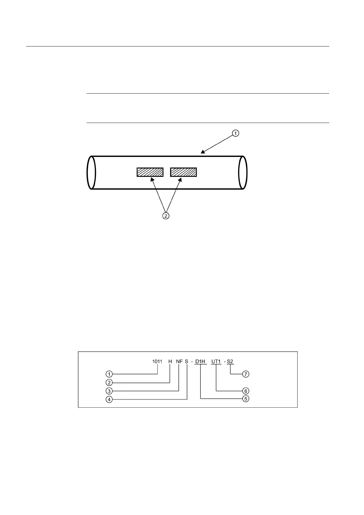
surface, if necessary, and remove any grit, corrosion, rust, loose paint, etc.
Use abrasive material provided to provide a clean contact surface for the sensors.
Note
Please note that
the instructions show vertical mounting for clarity purposes only. Do not
install sensors on the top of a pipe.
① Pipe
② Cleaned Areas
Figure 5-7 Pipe Surface Preparation
4. Clean an area 13 mm (1/2-inch) on either side of the sensors.
5. Clean an additional 13 mm (1/2-inch) along the length of the sensors.
5.2.2 Sensor Identification and Selection
Sensor identification
The sensor part number located on the front face provides a detailed identification. For
example, the Part Number:
1011HNFS-D1H-UT1-S2
means:
① Model ⑤ Size
② Hi Precision ⑥ Temperature
③ NEMA w/F-Conn ⑦ Agency Approved
④ Pipe Material
Connecting
5.2 Sensor Wiring
FUP1010 IP67 Portable Flowmeter
32
Operating Instructions, 02/2010, A5E02951522A Revision 01

 Loading...


