P1
P2
AUX
485-
485+
EXC-
EXC+
SEN-
SIG-
SIG+
SEN+
15
13
11
9
7
5
3
1
CI-
CI+
DQ.2
DQ.1
DQ.0
DI.2
DI.1
DI.0
16
14
12
10
8
6
4
2
L+ M
4A PWR
DIAG
LAN
24V
RJ45
Bus ASIC
15 LEDs
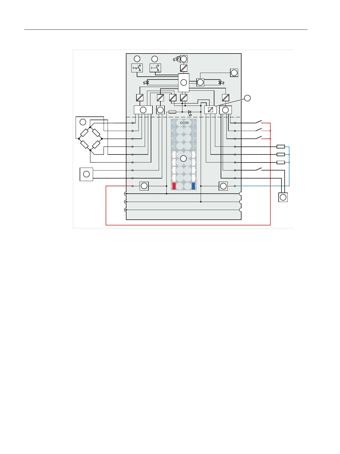
① Backplane bus interface ⑨ Color identification label CCxx (optional)
② MCU (microcontroller) ⑩ RS485 device
③ Ethernet sender/receiver (bus coupler) ⑪ Load cell
④ Ethernet ⑫ Filter and A/D converter
⑤ Output electronics ⑬ RS485 sender/receiver (bus coupler)
⑥ Input electronics ⑭ Write protection
⑦ External signal source for counter input CI ⑮ Setup mode
⑧ Filter connection supply voltage (only when
light-colored BaseUnit is present)
Figure 4-1 Principle and pin assignment
Digital inputs DI.0 to DI.2
Assign to the digital inputs scale functions free and individually within the DR 7. No functions
are assigned to the inputs at the factory.
The digital inputs are not isolated from each other.
Connecting
4.2 Connection to electronic weighing system
Technology module TM SIWAREX WP351 HF
26 Operating Instructions, 01/2020, A5E47521010-AA
 Loading...


