12
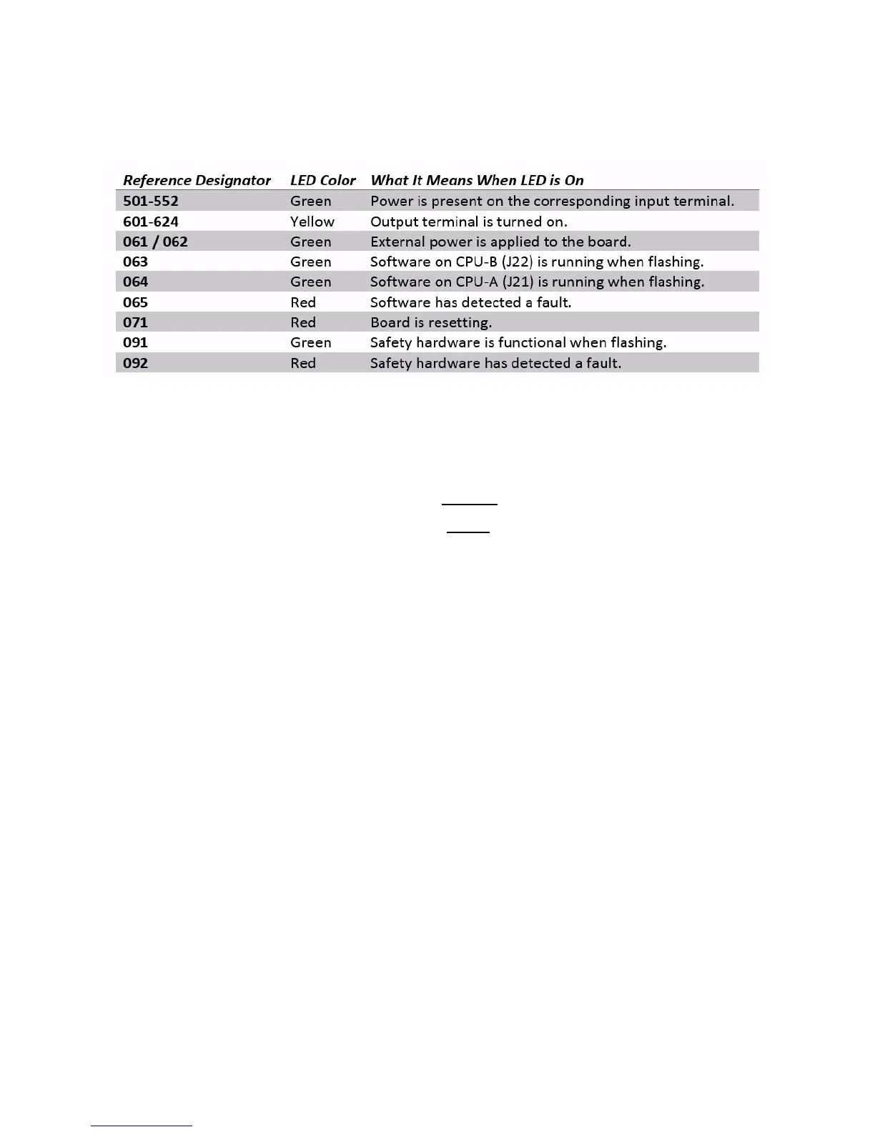
SRU LED Indicator Table
Each LED on the SRU board has a reference designator next to it. The table below
explains the function of each LED.
You will notice that the LEDs come in three colors: red, yellow, and green.
Red indicates a problem. Either a fault has been detected or the board is
resetting.
Yellow is used to indicate an active output terminal.
Green is used to show power on an input terminal, power to the board, and
as a “heartbeat” to show the software is running on the two processors.
The heartbeat is displayed by the CPU LEDs (063 and 064) which flash when
the board is functioning.
Inputs
The input terminals are labeled 501 through 548. Each terminal has a green LED
next to it which indicates when there is power present on the input. Inputs are
designed for DC current only. Putting AC current on an input will damage it.
Outputs
The yellow LED indicates the output transistor is on and current can flow
through the output terminal. The output terminal provides a reference (REF)
signal which means it will always connect to the negative side of the load. The
positive side of the load should be connected to a +24vDC power source.
** Never connect +24vDC directly to the output terminal. Without a load to
limit the current, the output transistor may be damaged. **
When the yellow LED is off, it means the output transistor is also off which
means any load connected to it will not be actuated.
 Loading...