92
BRAKE BOARD ADJUSTMENT
The adjustment procedure is the same for both the small and large
brake boards. The brake coils MUST be connected to the terminals to
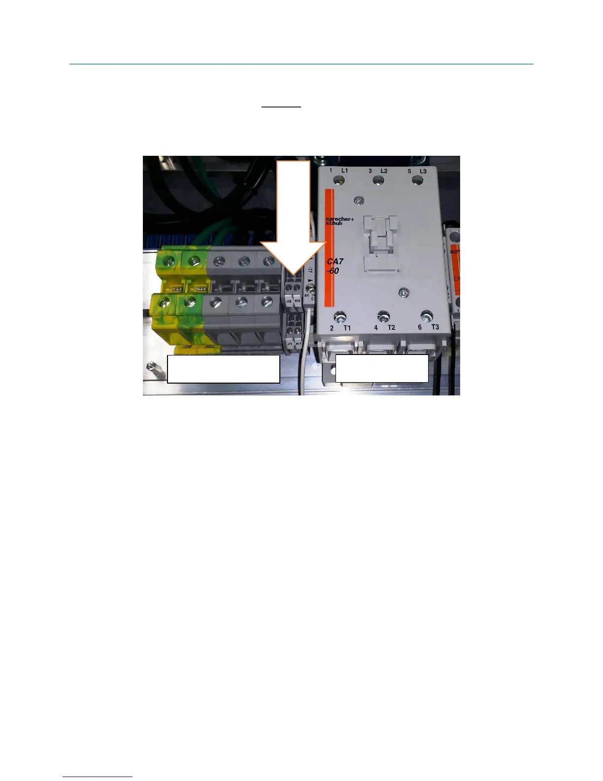
provide a load when measuring voltages. The brake terminals are
located between the M contactor and the L1~L3 main line terminals.
Adjustment Pot Descriptions
1. Pick Voltage
a. This pot adjusts the PICK voltage that the board initially
sends out to the brake coil to pick the brake.
2. Hold Voltage
a. This pot adjusts the HOLD voltage that keeps the brake
picked during running. This is usually lower than the Pick
voltage.
3. Pick-Hold Timer
a. This is the adjustable delay between the time the PICK
voltage activates and transitions to the HOLD voltage. This
timer can be adjusted as high as 3.5 seconds.
The location of the adjustment potentiometers are shown on the next
page: