145
MOVFR DOOR OPERATOR
NOTE: Verify that the voltage supplied to the door operator from breaker
DR in machine room matches the actual supply voltage (120vac / 240vac)
for the door operator before applying power.
Remove the Temporary Gate switch jumper when installing the Gate Switch circuit.
Remove Temporary DPM jumper at Cartop Input 519 when making permanent DPM
connection from Door Operator. If the DPM is not used then you can jump it to the Gate
Switch terminal. Check provided drawings for correct wiring.
A photoeye may be used as a separate input to the cartop controller or wired into the door
operator. This will need to be installed for the doors to operate correctly. If a photoeye is not
used then jump out the PHE Input to C24 (refer to provided drawings for proper Input
terminal).
Photoeyes can have main power of 24vdc or 120vac.
For 24vdc attach to C24 and REF.
For 120vac attach to 120 and N terminals. Note: Never connect a 120vac photoeye to the
terminals on the SRU board. THE SRU TERMINALS OPERATE ON 24VDC ONLY.
The normally closed contact (NC) can be connected between the door operator “reopen”
terminal and the PHE Input terminal or, if door operator doesn’t support a PHE, then connect
a jumper between C24 and the PHE Input terminal.
Push DIP Switch #3 (third from the top) to the ON position. This bypasses door operation and
hall calls which will be checked later in this procedure.
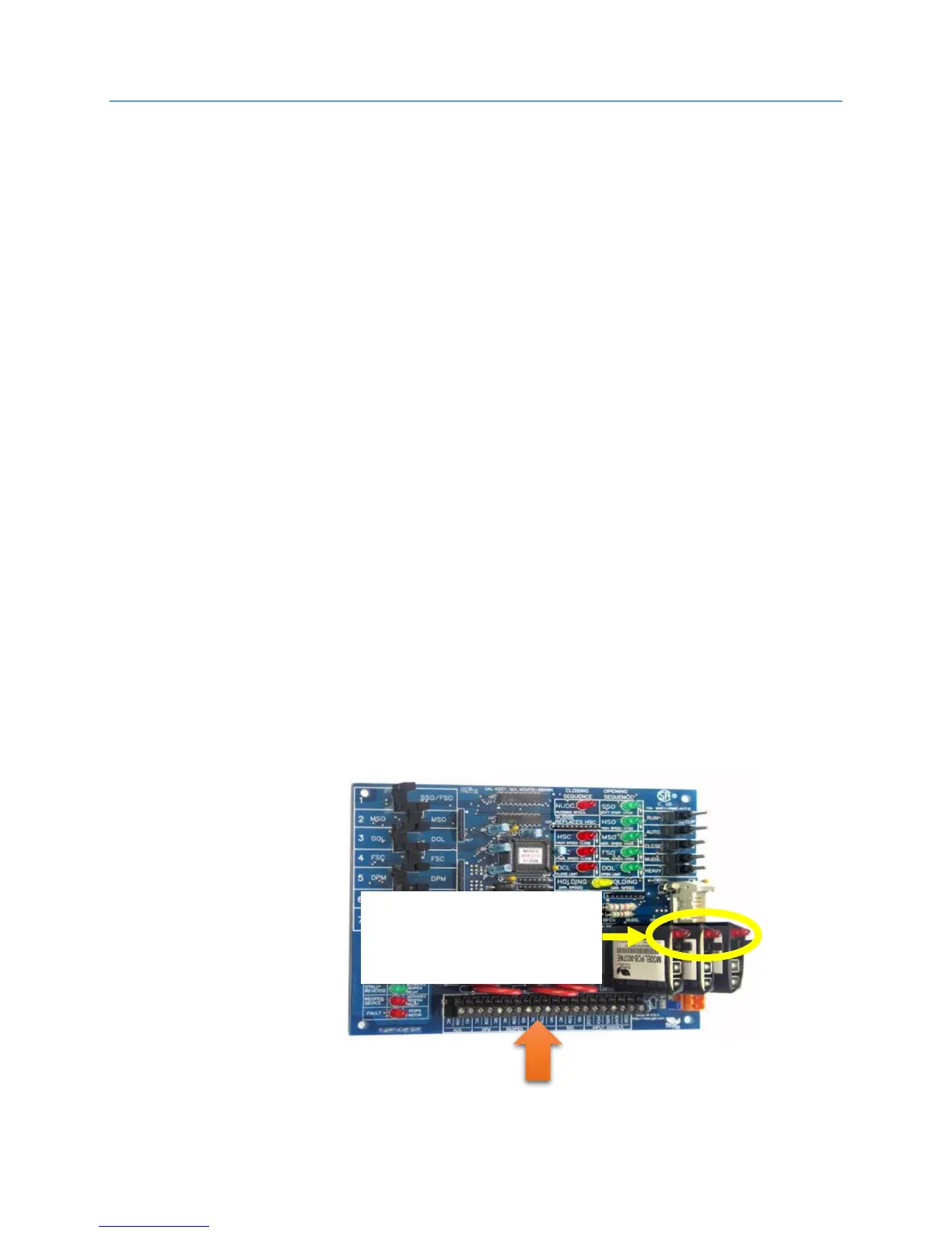
The MOVFR door operator requires jumpers to be removed when operated by the low
voltage from the Smartrise SRU. See the following figure for jumper location.
CAUTION: MAKE SURE YOU DON’T OVERTIGHTEN THE SCREW TERMINALS ON THE MOVFR
TERMINAL STRIP. DAMAGE TO THE CONTACT PIN CAN OCCUR.
Remove these jumpers to
work with the Smartrise
24vdc signals.