DMS-1200 Release 6 Operations Manual
Section 7 – DAS Device Control 54
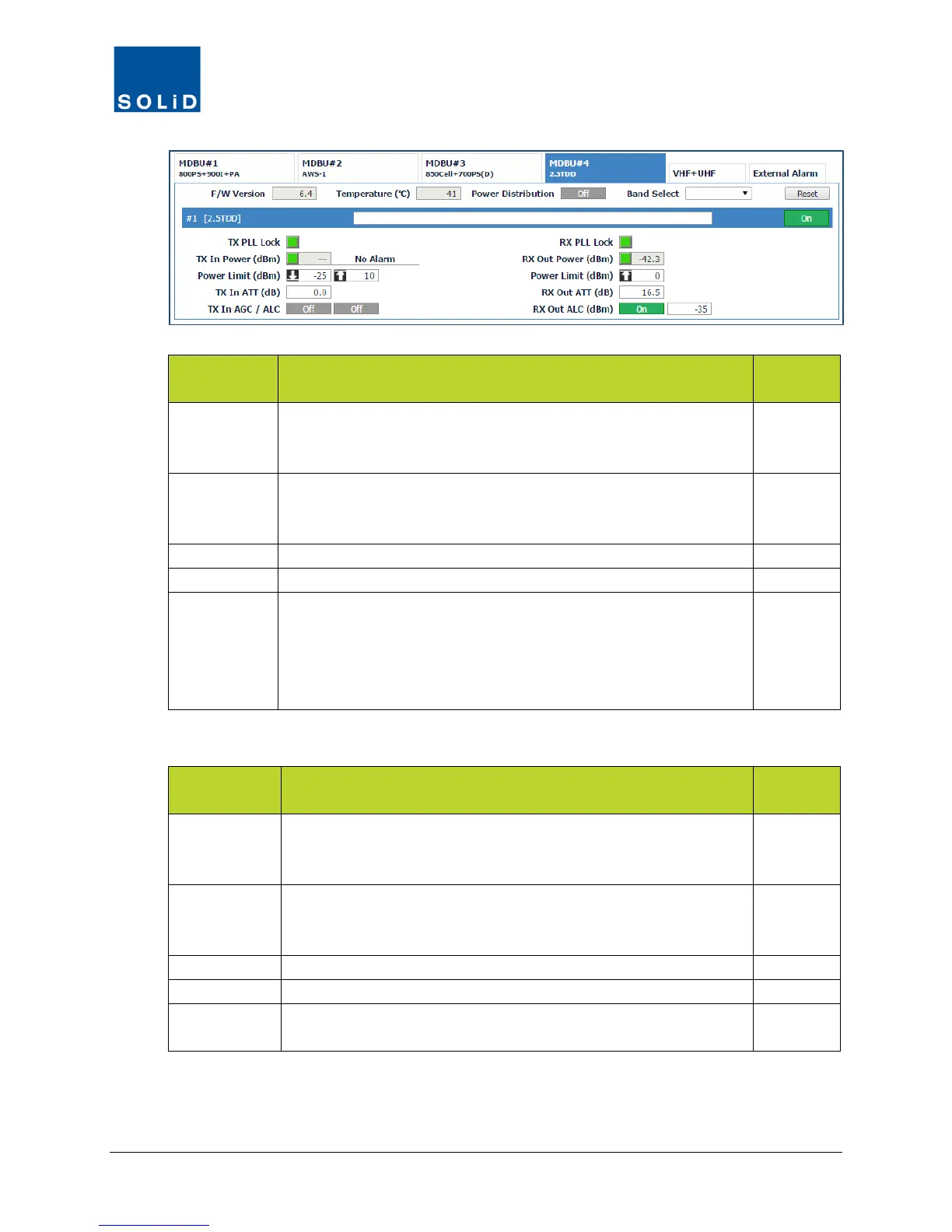
MDBU Field Description
User
Tx PLL Lock Tx Phase Locked Loop status.
Green = Normal (locked). Red = PLL unlocked.
(Not applicable to VHF/UHF setup.)
N
Tx In Power Shows Tx input power on that port (±2dB) and status: Green = within
high/low limits. Red = input power below / above limits.
(Displays --- when no input signal is detected.)
Y
Enter values for low / high power alarm limits.
Set attenuation level to be applied to input power. Max = 30 dB.
Tx In AGC /
ALC
Click toggle to turn Auto Gain Control and Auto Level Control On/Off.
Input AGC: The system optimizes BIU gain against each BIU input level.
Automatically turns off once complete.
Input ALC: Input ALC function can be used to limit input power if it
exceeds a predetermined level.
Y
Table 7.2 – MDBU Setup Screen Fields – TX Values
MDBU Field Action / Description
User
Rx PLL Lock Rx PLL (Phase Locked Loop) status.
Green = Normal (locked). Red = PLL unlocked.
(Not applicable to VHF/UHF setup.)
N
RX Out Power
Shows RX power: Green = Normal. Red = power exceeds limit.
Shows Rx out power on that port. Accuracy is ±2dB.
(Displays --- when no output signal is detected.)
Y
Set the high power limit.
Set attenuation level applied to Rx gain from the MDBU.
Rx Out ALC Click the toggle to turn Auto Level Control On/Off.
If on, system limits RX output power to indicated level.
Y
Table 7.3 – MDBU Setup Screen Fields – RX Values
3. Click Apply when you are done. Changes are saved immediately.