DMS-1200 Release 6 Operations Manual
Section 7 – DAS Device Control 55
7.2.3 External Alarm Setup (Optional)
Three dry contacts are located at the BIU back panel that can be used to support external alarms
for reporting conditions like a module failure, high temperature condition or power failure. These
alarms can be connected to the auxiliary input of the Base station or any other dry-contact
application.
The alarm level can be configured using the Management > Alarm Control menu.
ALM #1 and ALM#2 are output alarms only. ALM #3 can be configured for output or input. When
all ALMs are configured for output, an event indicates active output on the alarm. When an alarm
condition exists, the output relay terminal will operate as shown in the table.
1/ 2/ 3
Table 7.4 – External Alarm Relay Setup Screen Fields
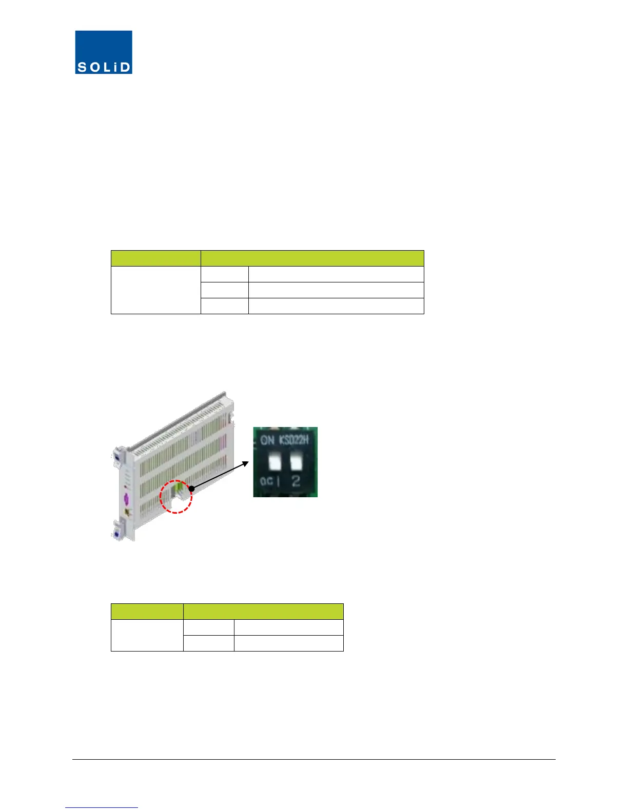
External ALM #3 can be used for output or input. An event indicates active output on the External
alarm or active input for the BIU Contact Alarm. To use the ALM #3 for input mode, make sure
the dipswitch position 1 and 2 on the MCPU are both set ON.
Figure 7.1 – MCPU Dipswitch
c. When input mode is selected, use the N.O and COM terminals as shown below.
3
Table 7.5 – External ALM #3 Input Mode Setup