DMS-1200 Release 6 Operations Manual
Section 7 – DAS Device Control 57
7.3 Setting ODU Parameters
The ODU Control screen allows you to monitor and manage settings for the ODU and the Donor
Optic Units (DOUs) in the ODU.
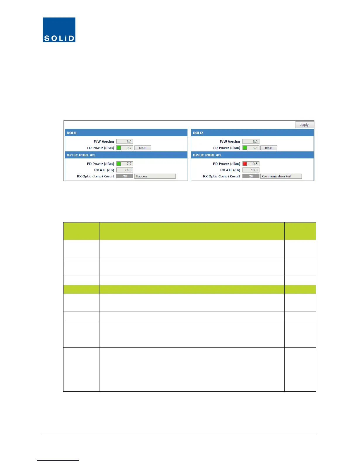
7.3.1 ODU / DOU Setup
1. In the Tree Menu or Menu bar, click the ODU you want to configure to load its control screen.
Active ports are lit in blue; inactive are greyed. Some fields show current settings and are not
user configurable. Other fields allow you to configure parameters for the device. You can see the
Min / Max values for the parameter by clicking in the field.
2. Configure each active port on the DOUs according to these guidelines:
DOU Fields Action / Description
User
F/W
Firmware version of DOU.
N
LD Power Displays laser diode power levels being transmitted to ROU or OEU.
Green = normal. Red = Power is below reference power current.
N
Click Reset to cycle power and reboot the DOU optic module.
PD Power Displays photo diode power being received from ROU or OEU. Green
= normal. Red = Received power falls below reference power level.
N
Displays attenuation level applied to receive (RX) side of the DOU.
Rx Optic
Comp
Click the toggle to turn On/Off the Auto optical loss compensation
function. The auto function applies same level of attenuation as the
TX Optic ATT of the ROU or OEU.
Y
Result Shows result after compensating for optical loss:
Success: optical compensation has been successful.
Over Optic Loss: optical loss generated exceeds limits: 6dBo or more
for 4-port DOU (OM4); 11dBo or more for 1-port DOU (OM1).
Fail: Communication between the DOU and ROU has failed.
N
Table 7.6 – ODU / DOU Setup Screen
3. Click Apply when you are done. Changes are saved immediately.