DMS-1200 Release 6 Operations Manual
Section 7 – DAS Device Control 65
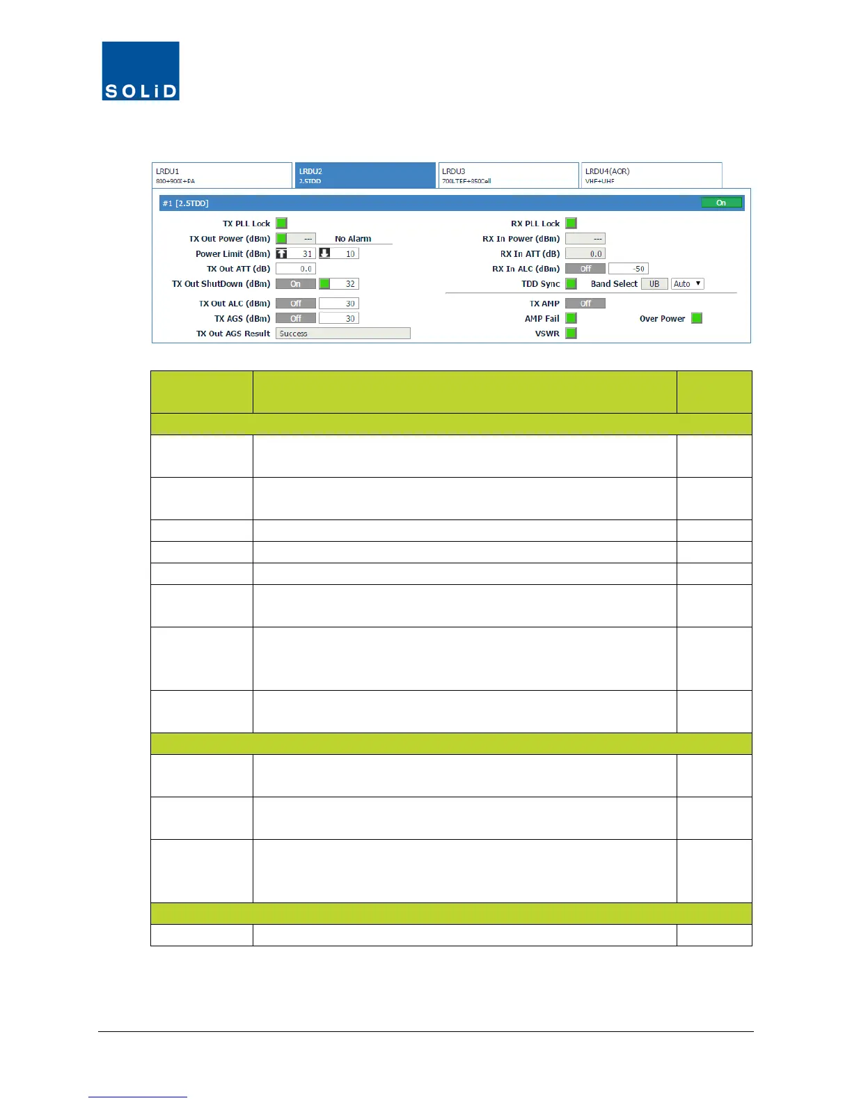
3. Configure the RX settings according to the following guidelines:
Field Action / Description
User
Rx PLL Lock Rx Phase Locked Loop status. Green = normal. Red = PLL
N
Rx In Power Shows Rx input power on that port (±2dB).
Displays --- when there is no input detected.
N
Shows attenuation level applied to Rx input power.
Turn On/Off Auto Limit Control for input power.
Turn On/Off high power amplifier. Click Reset to cycle amp power.
AMP Fail Shows amplifier status. Green = normal. Red = Power amplifier
loop has failed or unexpected low power detected.
N
VSWR Shows VSWR (Voltage Standing Wave Ratio) status and level.
Green = normal. Red = VSWR level has exceeded the pre-
N
Over Power Shows status of Over Power alarm. Green = normal. Red = Output
power level of the power amplifier has exceeded threshold.
N
TDD Sync Shows status of SDM (Sync Detection Module). Green = normal.
Red = module is not communicating properly.
N
Band Select Shows which TDD band was selected in the MDBU setup (see
page 53): Lower Band, Middle Band, or Upper Band.
N
For normal operation, from the drop down list, select Auto.
For CW or lab testing, use the drop down list to switch between
Low Band, Middle Band or Upper Band.
Y
From the Band Select list, select the desired UHF band.
Table 7.13 – LRDU Control Screen Fields – RX Value
4. Click Apply when you are done. Changes are saved immediately.