DMS-1200 Release 6 Operations Manual
Section 7 – DAS Device Control 67
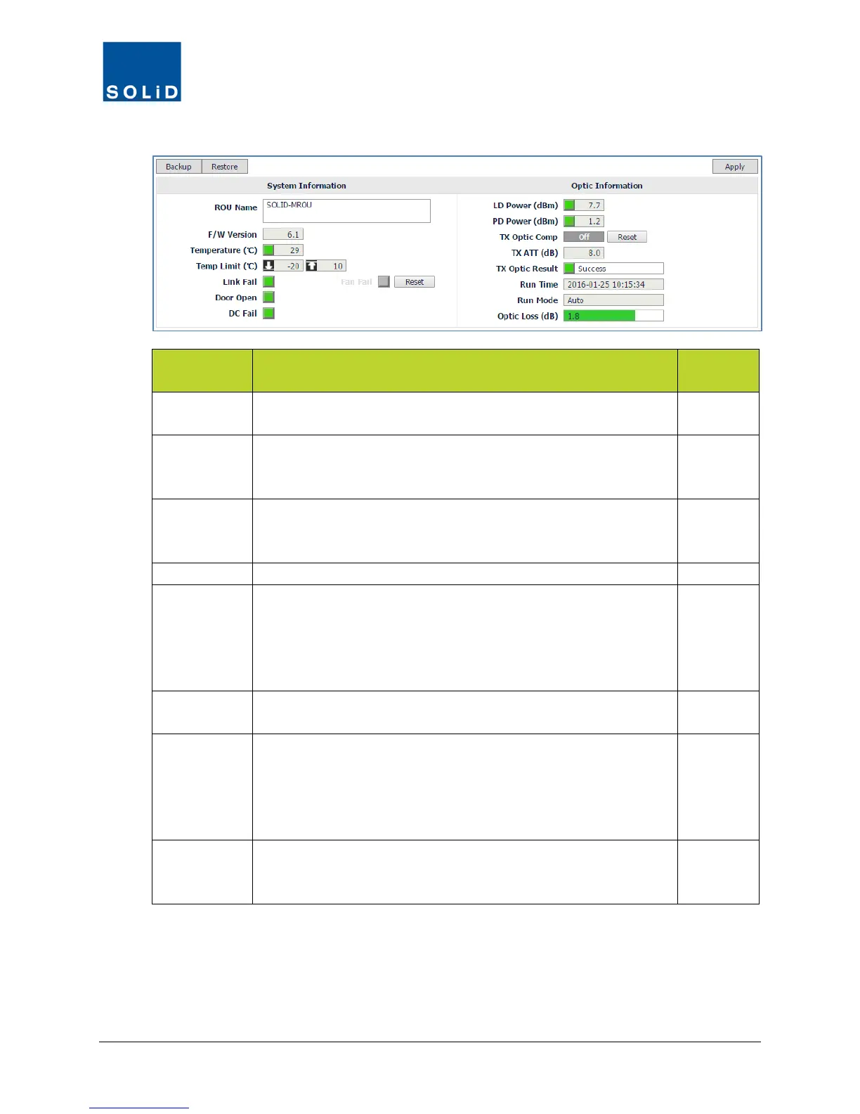
3. Configure the Optic Information according to the guidelines in following table:
ROU Field Action / Description
User
LD Power Shows laser diode power of R-Optic module. Green = normal
operation. Red = Power is below reference power.
N
PD Power Shows photo diode power being received from ODU or OEU.
Green = normal operation. Red = Receive power is below
N
Tx Optic
Comp
Turn On/Off Auto optic compensation function On/Off for transmit
signal. Click Reset to reset the link between the ODU and Remote
and recalculate optic compensation.
Y
Shows attenuation level for compensating optical loss.
Tx Optic
Result
Shows result after running Auto optic compensation:
Success: The optical compensation has been successful.
Over Optic Loss: optical loss exceeds limits: 6dBo or more for 4-
port optic module; 11dBo or more for 1-port optic module.
Communication Fail: Communication with BIU has failed.
N
Run Time Displays date/time and mode of most recent optic compensation
N
Run Mode Shows optical compensation mode:
Auto: Optical compensation was executed by the CPU
automatically.
Manual: Optical compensation was executed manually by the
N
Optic Loss Displays optical loss. Green = optical loss is within tolerance.
Red = optical loss exceeds limits: 9dB for 1-port optic module; 4dB
N
Table 7.15 – MROU Control Screen Fields – Optic Information
4. Click Apply when you are done. Changes are saved immediately.