DMS-1200 Release 6 Operations Manual
Section 7 – DAS Device Control 69
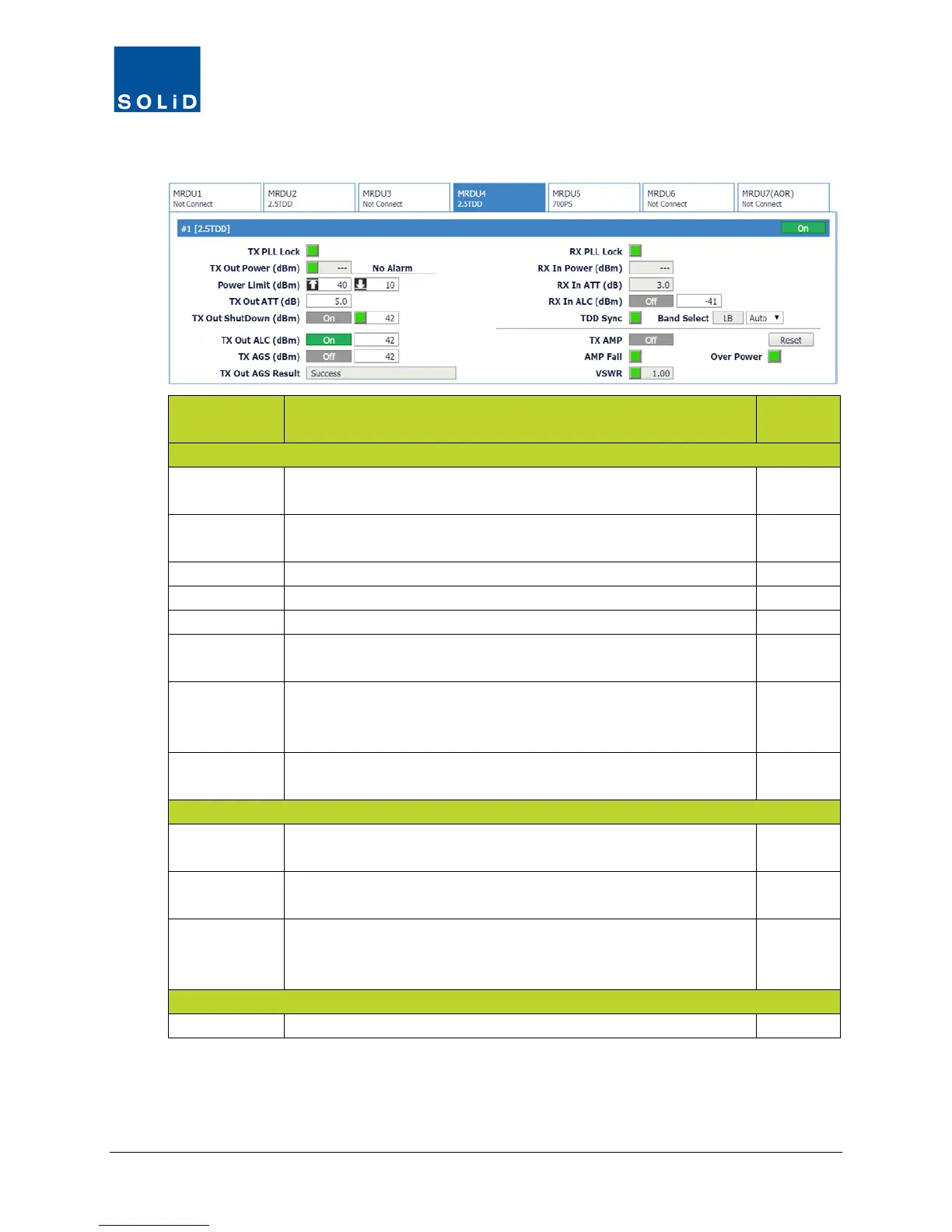
3. Configure the RX settings according to these guidelines:
Field Action / Description
User
Rx PLL Lock Rx Phase Locked Loop status. Green = normal. Red = PLL
N
Rx In Power Shows Rx input power on that port (±2dB).
Displays --- when no input detected.
N
Shows attenuation level applied to Rx input power.
Turn On/Off Auto Limit Control for input power.
Turn On/Off high power amplifier. Click Reset to cycle amp power.
AMP Fail Shows amplifier status. Green = normal. Red = Power amplifier
loop has failed or unexpected low power detected.
N
VSWR Shows VSWR (Voltage Standing Wave Ratio) status and level.
Green = normal. Red = VSWR level has exceeded the pre-
N
Over Power Shows status of Over Power alarm. Green = normal. Red = Output
power level of the power amplifier has exceeded threshold.
N
TDD Sync Shows status of SDM (Sync Detection Module). Green = normal.
Red = module is not communicating properly.
N
Band Select Shows which TDD band was selected in the MDBU setup (see
page 53): Lower Band, Middle Band or Upper Band.
N
For normal operation, from the drop down list, select Auto.
For CW or lab testing, you can use the drop down list to switch
between Low Band, Middle Band or Upper Band.
Y
From the Band Select list, select the desired UHF band.
Table 7.17 – MRDU Control Screen Fields – RX Value
4. Click Apply when you are done. Changes are saved immediately.