5-20
6. Optical Axis Adjustment
Align the lens Optical Axis with that of the CCD imager. If deviated,
center of picture can lose focus when zoom is operated from the
WIDE end to the TELE end.
Subject Siemens star
Measurement Point Check on the monitor TV
Measuring Instrument
Adjustment Page F E
Adjustment Address 69 D0, DE
Switch setting:
1) POWER.................................................................. CAMERA
Preparations before adjustments:
1) Playback the monoscope segment of the system check tape
(XH5-5 (NTSC), XH5-5P (PAL)).
2) Attach the optical axis frame chart (transparent) on the monitor
TV screen. Center of monoscope image and that that of optical
axis frame must be agree.
3) Set to the camera mode.
Adjusting method:
1) Select page: 0, address: 01, and set data: 01.
2) Select page: 6, address: 40, and set data: 02.
3) Select page: 6, address: 41, and set data: 01.
4) Input the data of Table 5-1-9 to each adjustment addresses.
Note: Press the PAUSE button each time to set the data.
Table. 5-1-9.
5) Place the Siemens star 2.0 m away from the front of the lens.
6) Shoot the Siemens star with the zoom TELE end.
7) Point the lens toward the Siemens star chart until center of the
Siemens star is located in the center of the optical axis frame.
8) Shoot the Siemens star with the zoom WIDE end.
9) Measure on the monitor TV screen in which area of the optical
axis frame the center of the Siemens star is located. Measure
the amount of displacement (distance between the center of
the Siemens star and the center of the optical axis frame.) The
measurement value is named L1.
10) Read the correction data corresponding to the area from Table
5-1-10.
11) Input the correction data to each adjustment address.
Note: Press the PAUSE button each time to set the data.
12) Shoot the Siemens star with the zoom TELE end.
13) Point the lens toward the Siemens star chart until center of the
Siemens star is located in the center of the optical axis frame.
14) Shoot the Siemens star with the zoom WIDE end.
15) Measure the amount of displacement (distance between the
center of the Siemens star and the center of the optical axis
frame.) The measurement value is named L2.
16) Compare the values L1 and L2, and confirm that L2 is smaller
than L1. If L2 is lager than L1, input the data of Table 5-1-9 to
each adjustment address.
Note: Press the PAUSE button each time to set the data.
Note: NTSC model: DCR-PC9
PAL model: DCR-PC6E/PC9E
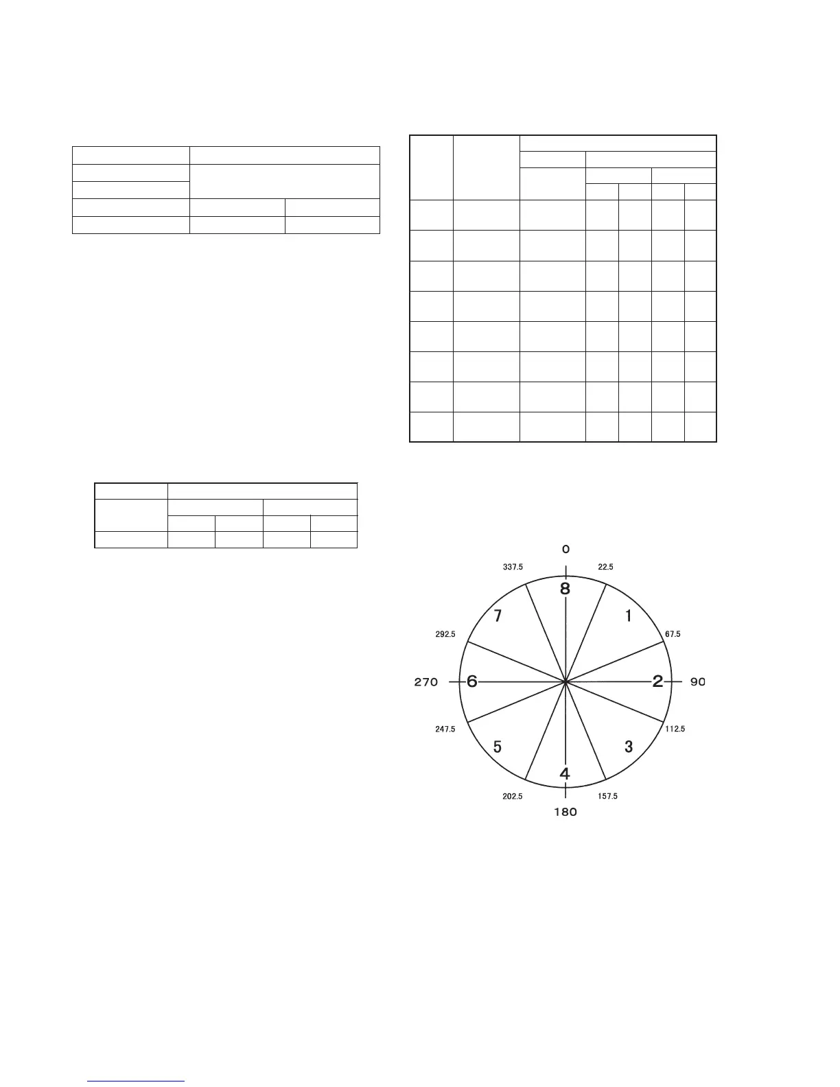
Table. 5-1-10.
Processing after Completing Adjustments:
1) Select page: 0, address: 01, and set data: 00.
2) Select page: 6, address: 40, and set data: 00.
3) Select page: 6, address: 41, and set data: 00.
Area
1
2
3
4
5
6
7
8
Display
phase
22.6° to
67.5°
67.6° to
112.5°
112.6° to
157.5°
157.6° to
202.5°
202.6° to
247.5°
247.6° to
292.5°
292.6° to
337.5°
337.6° to
22.5°
Connection data
Page: F
Address: 69
00
Address: D0
NTSC PAL
22 26
Address: DE
NTSC PAL
5F 71
Page: E
Page: F
Address: 69
01
02
03
04
05
06
07
08
Address: D0
NTSC PAL
22 26
22 26
22 26
02 26
22 26
22 26
22 26
02 26
Address: DE
NTSC PAL
57 69
5F 71
67 79
69 7D
67 79
5F 71
57 69
55 65
Page: E
Fig. 5-1-8.