2-7
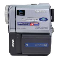
2-10.BJ-002/002A BOARD
1 Four screws
(M1.7 × 4),
lock ace, p2
8 Screw
(M1.7 × 4),
lock ace, p2
4 Screw
(M1.7 × 2.5)
7 Screw
(M1.7 × 2.5)
2 Tripod screw
3 Bottom
frame
9 Tapping screw
(M1.7 × 4)
qd Two tapping
screws (M1.7 × 4)
q; Terminal ratainer
plate assembly
qa Battery terminal board
qs DC-IN
connector
qf BJ-002 board (PC9/PC9E)
BJ-002A board (PC6E)
5 PD-113 harness (16P)
6 PR-063 harness (8P)
CN3100 (for the DC-IN connector) and CN3105 (for the battery terminal board) of BJ-002/002A
board are the same size, and the number of the pins is the same.
So these connectors may be mistaken for each other. When these connectors are mistaken,
the charge system of the unit may break.
So ascertain the color of the connector when assembling these connectors.
Note 1:
BJ-002/002A board
Battery terminal board
CN3100 (for the DC-IN connector) ················· Blue
CN3105 (for the battery terminal board) ········ White
DC-IN connector
CN3100 (Blue)
CN3105 (White)
(Note 1)
(Note 1)
(Note 1)
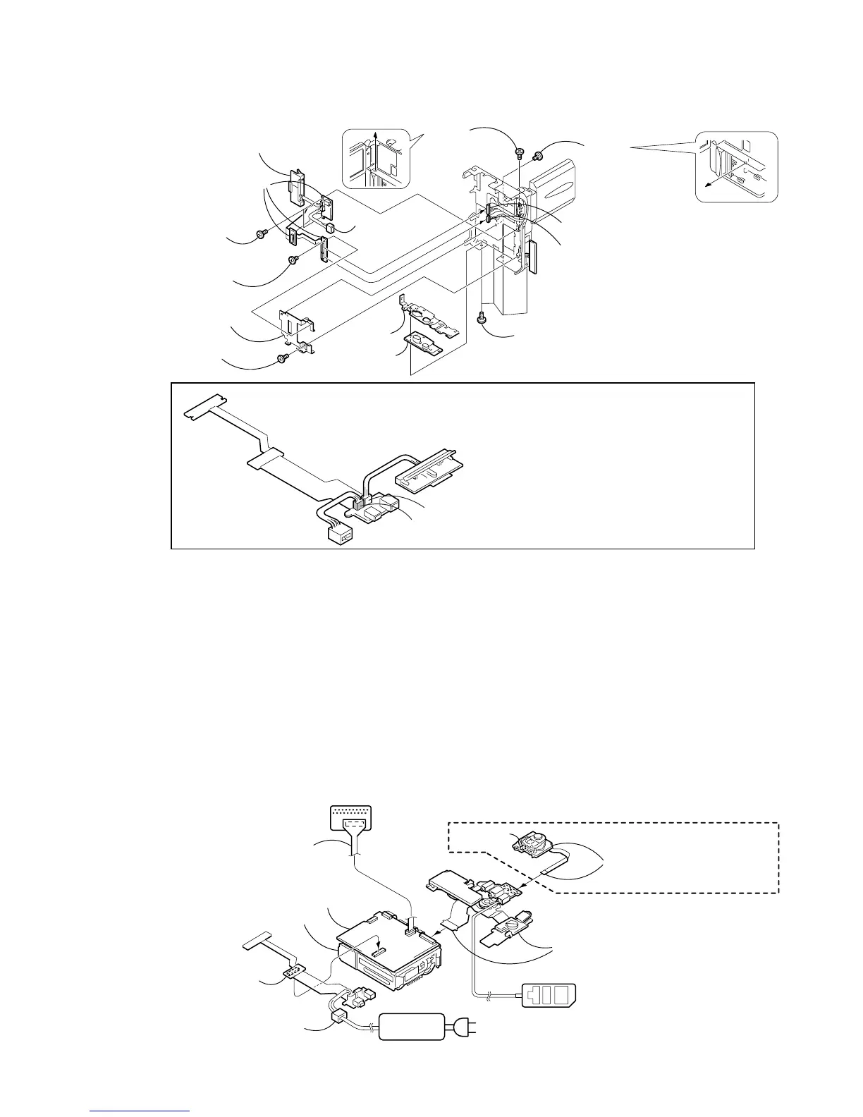
VC-265
Adjustment remote
commander (RM-95)
CPC-6 flexible jig
(J-6082-370-B)
CPC-6 terminal board jig
(J-6082-371-A)
When exiting the “Forced VTR Power ON” mode, connect the control
switch block (PS-1770) to the control switch block (FK-1770). Or,
when ejecting the cassette, connect the control switch block (PS-1770)
to the control switch block (FK-1770) and press the EJECT switch.
Control switch block
(PS-1770) (8P)
Control switch block (FK-1770)
(A-7096-840-A) (51P)
(Note 2)
Eject switch
VC-265 board (PC9/PC9E)
VC-265A board (PC6E)
Mechanism deck
AC IN
AC power
adaptor
DC-IN connector
[SERVICE POSITION TO CHECK THE VTR SECTION]
Connection to Check the VTR Section
To check the VTR section, set the VTR to the “Forced VTR power ON” mode. (Or, connect the control switch block (PS-1770)
to the control switch block (FK-1770) and set the power switch to the “VIDEO” position.)
Operate the VTR function using the adjustment remote commander (with the HOLD switch set in the OFF position).
Note 2 : The control switch block (FK-1770) is used for the repair parts as a jig.
Setting the “Forced VTR Power ON” mode
1) Select page: 0, address: 01, and set data: 01.
2) Select page: D, address: 10, set data: 02 and
press the PAUSE button of the adjustment remote
commander.
Exiting the “Forced VTR Power ON” mode
1) Select page: 0, address: 01, and set data: 01.
2) Select page: D, address: 10, data: 00, and press the PAUSE
button of the adjustment remote commander.
3) Select page: 0, address: 01, and set data: 00.
BJ-002 board (PC9/PC9E)
BJ-002A board (PC6E)
(60P)