5-27
1-4. COLOR ELECTRONIC VIEWFINDER
SYSTEM ADJUSTMENT
Note1: When replacing the LCD unit, be careful to prevent damages
caused by static electricity.
Note2: Perform the following data setting before the viewfinder system
adjustments.
1) Select page: 2, address: 0E, and set data: 67.
2) Select page: 2, address: 0F, and set data: 01.
Reset the data after completing adjustment.
1) Select page: 2, address: 0E, and set data: 00.
2) Select page: 2, address: 0F, and set data: 00.
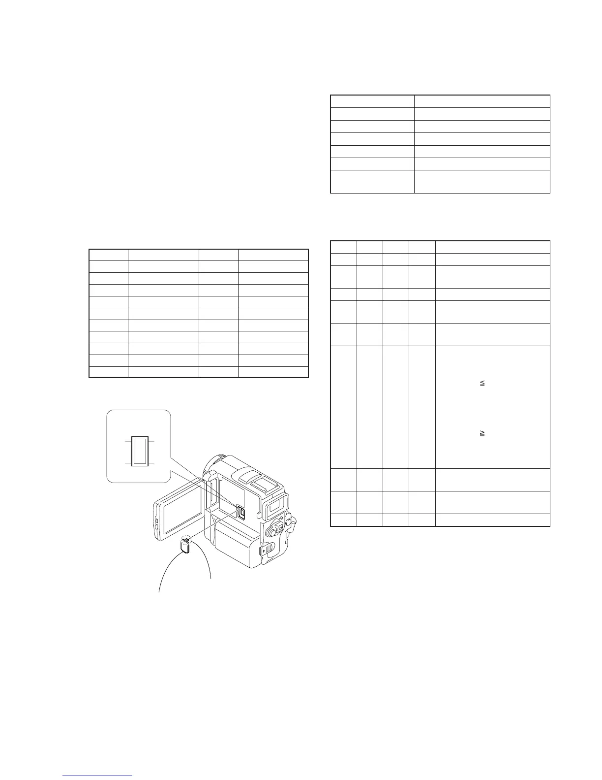
[Adjusting connector]
Most of the measuring points for adjusting the viewfinder system
are concentrated in CN004 of the VC-265 board.
Connect the Measuring Instruments via the CPC-6 flexible jig (J-
6082-370-B) and CPC-6 terminal board jig (J-6082-371-A).
The following table shows the Pin No. an2 signal name of CN004.
Table 5-1-11.
1. VCO Adjustment (VC-265 board)
Set the VCO free-run frequency. If deviated, the EVF screen will be
blurred.
Mode Camera
Subject Arbitrary
Measurement Point Pin 5 of CN004 (EVF VCO)
Measuring Instrument Frequency counter
Adjustment Page D
Adjustment Address 92, 93
Specified Value f = 15734 ± 30Hz (NTSC)
f = 15625 ± 30Hz (PAL)
Note1: NTSC: DCR-PC9
PAL: DCR-PC6E/PC9E
Adjusting method:
Order Page
Address
Data Procedure
1 0 01 01 Set the data.
2 D 92 Change the data and set the VCO
frequency (f) to the specified value.
3 D 92 Press PAUSE button.
4 D 92 Read the data, and this data is
named D92.
5 Convert D92 to decimal notation,
and obtain D92’. (Note2)
6 Calculate D93’ using following
equations (Decimal calculation)
NTSC model:
When D92’ 230
D
93’= D92’+ 25
When D92’ > 230
D93’= 255
PAL model:
When D92’ 25
D93’ = D92’– 25
When D92’ < 25
D93’ = 00
7 Convert D93’ to a hexadecimal
number, and obtain D93. (Note2)
8 D 93 D93 Set the data, and press PAUSE
button.
9 0 01 00 Set the data.
Note2: Refer to “Table 5-4-1. Hexadecimal-decimal Conversion Table”.
Pin No.
1
3
5
7
9
11
13
15
17
19
Signal Name
LANC SIG
EVF LED DA
EVF VCO
TW PWE
HI RXD
HI TEST A
TCK
JIG TDO
SWP
GND
Pin No.
2
4
6
8
10
12
14
16
18
20
Signal Name
EVF VG
GND
HI XRESET
HI TXD
TMS
JIG TDI
GND
RF IN/LANC JACK IN
RF MON
Fig. 5-1-14.
1
Claw
21
20 19
CN004
2
CPC lid