5-7
1-1-3. Precaution
1. Setting the Switch
Unless otherwise specified, set the switches as follows and perform adjustments without loading cassette.
1. POWER (PS-1770 block) ...................................... CAMERA
2. NIGHT SHOT (Lens block) ............................................OFF
3. FUNCTION settings of the touch panel
DIGITAL EFFECT .....................................................OFF
EXPOSURE ................................................................OFF
MANUAL SET of the MENU settings
PROGRAM AE ................................................ AUTO
PICTURE EFFECT ..............................................OFF
WHITE BALANCE.......................................... AUTO
CAMERA SET of the MENU settings
DIGITAL ZOOM..................................................OFF
16:9 WIDE ............................................................OFF
STEADY SHOT ...................................................OFF
SETUP MENU of the MENU settings
DEMO MODE......................................................OFF
4. FOCUS (FK-1770 block)............................................ Manual
5. BACK LIGHT (FK-1770 block)......................................OFF
2. Order of Adjustments
Basically carry out adjustments in the order given.
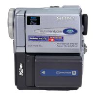
Fig.5-1-4.
3. Subjects
1) Color bar chart (Color reproduction adjustment frame)
When performing adjustments using the color bar chart, adjust
the picture frame as shown in Fig. 5-1-4. (Color reproduction
adjustment frame)
2) Clear chart (Color reproduction adjustment frame)
Remove the color bar chart from the pattern box and insert a
clear chart in its place. (Do not perform zoom operations during
this time.)
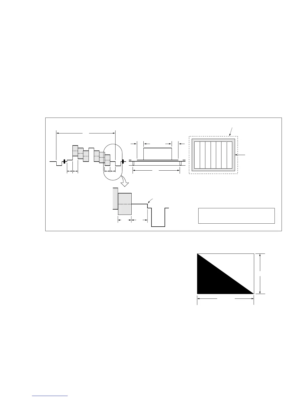
3) Flange back adjustment chart
Make the chart shown in Fig. 5-1-5 using A0 size (1189mm ×
841mm) black and white vellum paper.
Fig. 5-1-5.
Note: Use matte vellum paper bigger than A0, and make sure the edges of
the black and white paper joined together are not rough.
H
A=B
C=D
AB B
CD
A
Enlargement
V
Electronic beam scanning frame
CRT picture frame
B
A
Difference in level
Yellow
Cyan
Green
White
Magenta
Red
Blue
Yellow
Cyan
Green
White
Magenta
Red
Blue
Color bar chart (Color reproduction adjustment frame )
Fig. a
(Video output terminal
output waveform)
Fig. b (TV monitor picture)
Adjust the camera zoom and direction to
obtain the output waveform shown in Fig. a
and the TV monitor display shown in Fig. b.
White
Black
841m