5-47
3-4. VIDEO SYSTEM ADJUSTMENTS
Before perform the video system adjustments, check that the
specified value of “36MHz Origin Oscillation Adjustment” of
“CAMERA SYSTEM ADJUSTMENT” is satisfied.
1. Chroma BPF f0 Adjustment (VC-265 board)
Set the center frequency of IC801 chroma band-pass filter.
Mode Camera
Subject All black
(Cover the lens with the lens cap)
Measurement Point CH1: Chroma signal terminal of
S VIDEO jack (75Ω terminated)
CH2: Y signal terminal of S VIDEO
jack (75Ω terminated)
Measuring Instrument Oscilloscope
Adjustment Page C
Adjustment Address 28
Specified Value A = 100mVp-p or less
B = 200mVp-p or more
Adjusting method:
Order Page
Address
Data Procedure
1 0 01 01 Set the data.
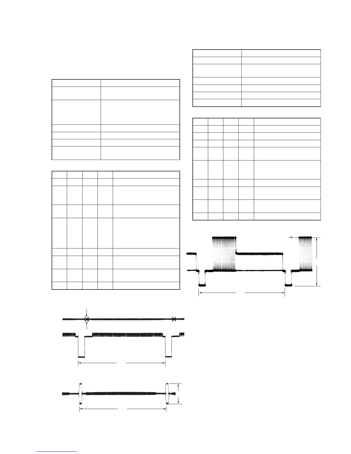
2 Check that the burst signal (B) is
output to the chroma signal
terminal of S VIDEO jack.
3 3 0C 04 Set the data, and press PAUSE
button.
4 C 28 Change the data for minimum
amplitude of the burst signal
level (A).
(The data should be “00” to
“0F”.)
5 C 28 Press PAUSE button.
6 3 0C 00 Set the data, and press PAUSE
button.
7 Check that the burst signal level
(B) satisfies the specified value.
8 0 01 00 Set the data.
2. S VIDEO OUT Y Level Adjustment (VC-265 board)
Mode Camera
Subject Arbitrary
Measurement Point Y signal terminal of S VIDEO jack
(75Ω terminated)
Measuring Instrument Oscilloscope
Adjustment Page C
Adjustment Address 25
Specified Value A = 1000 ± 14mV
Adjusting method:
Order Page
Address
Data Procedure
1 0 01 01 Set the data.
2 2 35 Note down the data.
3 2 35 01 Set the data.
4 3 0C 02 Set the data, and press PAUSE
button.
5 C 25 Change the data and set the Y
signal level (A) to the specified
value.
6 C 25 Press PAUSE button.
7 3 0C 00 Set the data, and press PAUSE
button.
8 2 35 Set the data that is noted down at
step 2.
9 0 01 00 Set the data.
CH1
CH2
A
H
CH1
H
B
When the data of page: 3, address: 0C, is 04:
When the data of page: 3, address: 0C, is 00:
Fig. 5-3-7.
H
Center of luminance line
A
Fig. 5-3-8.