5-28
2. Backlight Adjustment (VC-265 board)
Set the backlight luminance.
If deviated, the image may become dark or bright.
Mode Camera
Subject Arbitrary
Measurement Point Pin 3 of CN004 (EVF LED DA)
Measuring Instrument Digital voltmeter
Adjustment Page D
Adjustment Address 90, 91
Specified Value DCR-TRV6E:
A=1.50 ± 0.05Vdc
DCR-TRV9/TRV9E:
A=2.15 ± 0.05Vdc
Adjusting method:
Order Page
Address
Data Procedure
1 0 01 01 Set the data.
2 D 91 Change the data and set the voltage
(A) of Pin 3 of CN004 to the
specified value.
3 D 91 Press PAUSE button.
4 Read the data, and this data is
named D91.
5 Convert D91 to decimal notation,
and obtain D91’. (Note)
6 Calculate D90’ using following
equation. (Decimal calculation)
DCR-TRV6E:
D90’ =D91’ – 64
DCR-TRV9/TRV9E:
D
90’ =D91’– 96
7 Convert D90’ to a hexadecimal
number, and obtain D90. (Note)
8 D 90 D90 Set the data, and press PAUSE
button.
9 0 01 00 Set the data.
Note: Refer to “Table 5-4-1. Hexadecimal-decimal Conversion Table”.
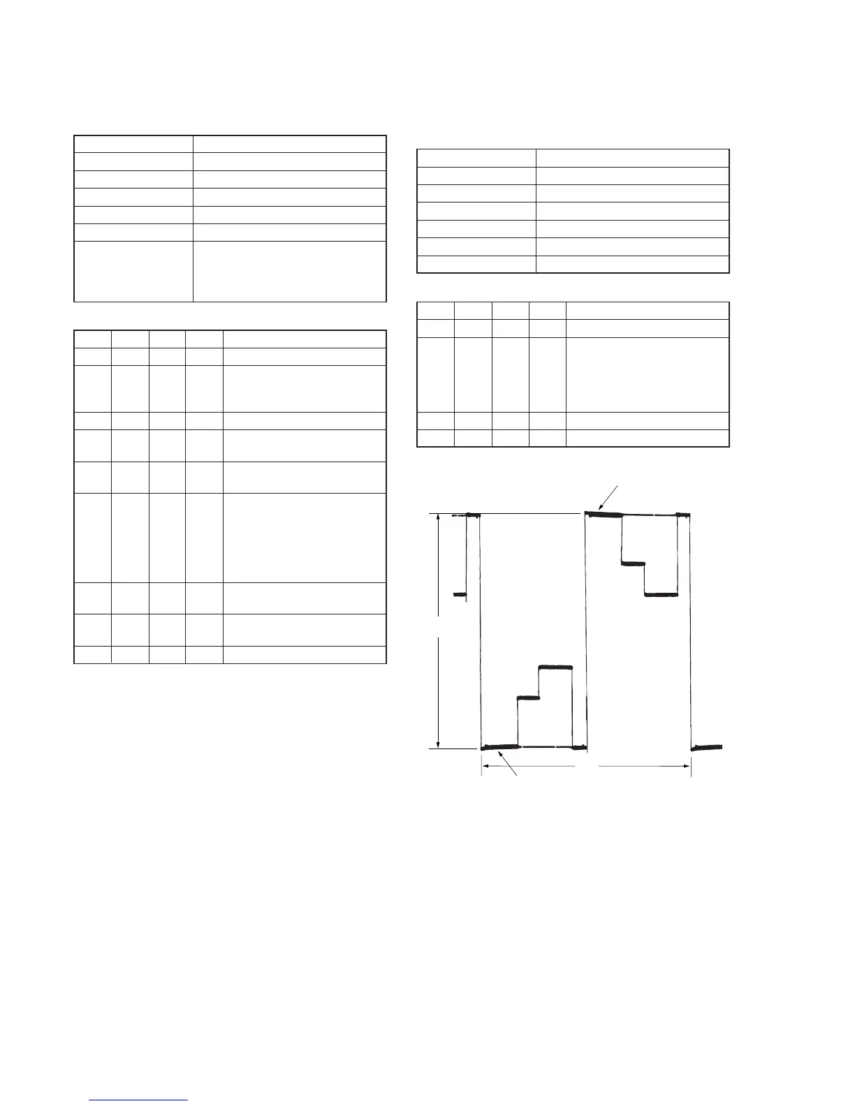
3. Bright Adjustment (VC-265 board)
Set the D range of the RGB decoder used to drive the LCD to the
specified value. If deviated, the LCD screen will become blackish
or saturated (whitish).
Mode Camera
Subject Arbitrary
Measurement Point Pin 4 of CN004 (EVF VG)
Measuring Instrument Oscilloscope
Adjustment Page D
Adjustment Address 95
Specified Value A = 7.00 ± 0.05V
Adjusting method:
Order Page
Address
Data Procedure
1 0 01 01 Set the data.
2 D 95 Change the data and set the
voltage (A) between the reversed
waveform pedestal and non-
reversed waveform pedestal to the
specified value.
3 D 95 Press PAUSE button.
4 0 01 00 Set the data.
Fig. 5-1-15.
Pedestal
Pedestal
A
2H