5-31
2. Bright Adjustment (PD-148 board)
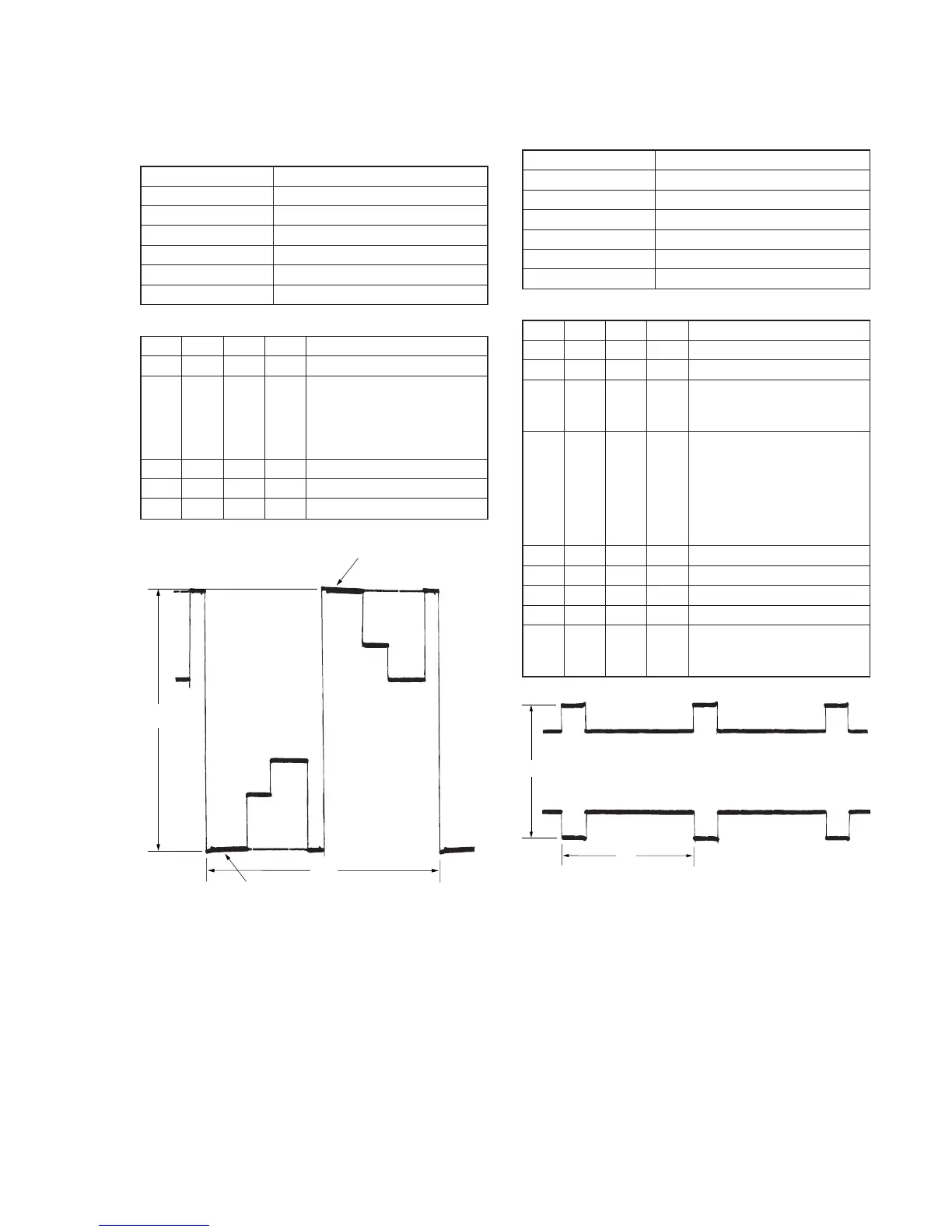
Set the video signal level for driving the LCD to the specified value.
If deviated, the LCD screen will become blackish or saturated
(whitish).
Mode VTR stop
Signal No signal
Measurement Point Pin 1 of CN2105 (VG)
Measuring Instrument Oscilloscope
Adjustment Page D
Adjustment Address A5
Specified Value A = 7.90 ± 0.05V
Adjusting method:
Order Page
Address
Data Procedure
1 0 01 01 Set the data.
2 D A5 Change the data and set the
voltage (A) between the reversed
waveform pedestal and non-
reversed waveform pedestal to the
specified value.
3 D A5 Press PAUSE button.
4 0 01 00 Set the data.
5
Perform “Black Limit Adjustment”
3. Black Limit Adjustment (PD-148 board)
Set the video signal level for driving the LCD to an appropriate
level.
Mode VTR stop
Signal No signal
Measurement Point Pin 6 of CN2105 (PSIG)
Measuring Instrument Oscilloscope
Adjustment Page D
Adjustment Address A6
Specified Value A = 8.50 ± 0.05V
Adjusting method:
Order Page
Address
Data Procedure
1 0 01 01 Set the data.
2 2 0E 61 Set the data.
3 2 0F Set the following data.
5B: DCR-PC9 (NTSC)
53: DCR-PC6E/PC9E (PAL)
4DA6
Change the data and set the PSIG
signal amplitude (A) to the specified
value.
[DCR-PC9/PC9E]
The data should be “00” to “0F”.
[DCR-PC6E]
The data should be “20” to “2F”.
5 D A6 Press PAUSE button.
6 2 0E 00 Set the data.
7 2 0F 00 Set the data.
8 0 01 00 Set the data.
9
Check that the specified value of
“Bright Adjustment” is satisfied. If
not, perform “Bright Adjustment”.
Fig. 5-1-18.
Fig. 5-1-19.
Pedestal
Pedestal
A
2H