1 Screw
(M1.7 × 2.5)
4 Screw (M1.7 × 2.5)
2 Tapping
screw
(M1.7 × 5)
9
3 Blind plate assembly,
PO-007 board
5 Two claws
7 Claw
6 Hinge cover (rear)
8 Hinge cover (front)
2 PD-113 harness
4 LCD hinge assembly
1 PR-063 harness
Harness
(black)
Harness
(black)
Harness
(black)
Harness
(black)
Harness
(gray)
Harness
(gray)
Harness
(gray)
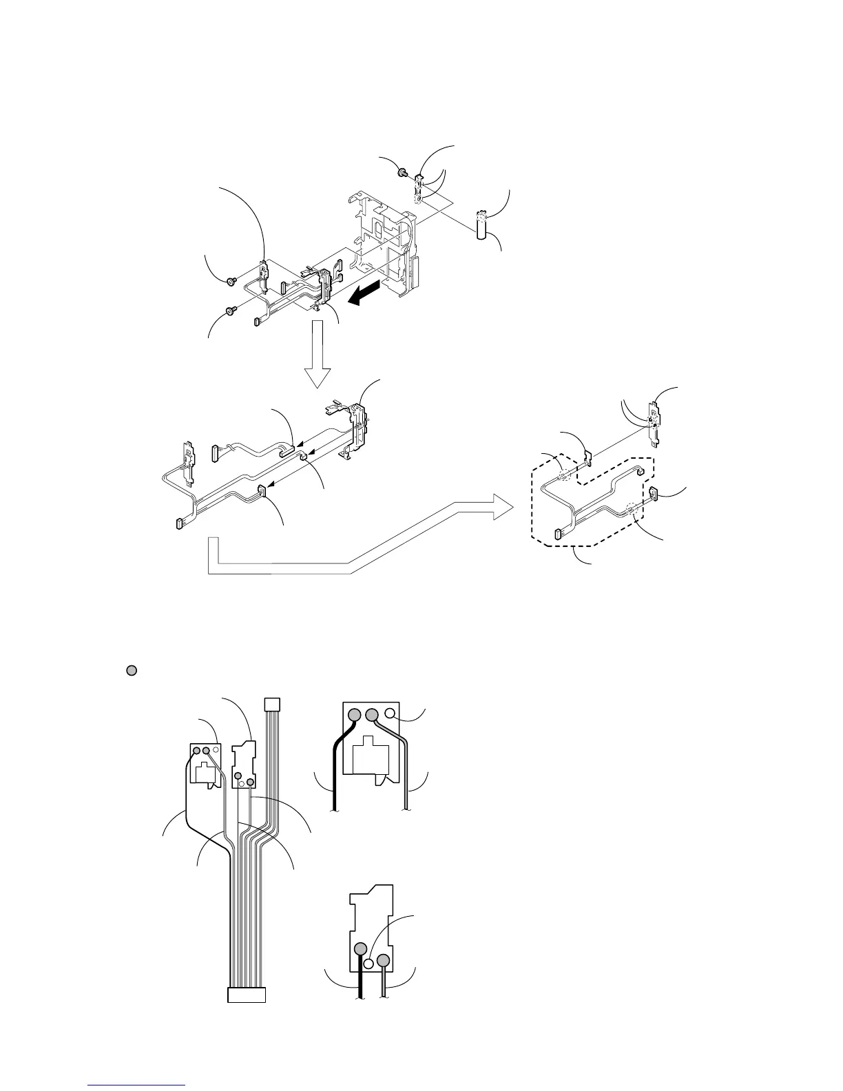
Boss hole
1 Connect the black harness at the leftmost end of the
harness (PR-063) and connect the second gray harness
(PR-063) to the PR-037 board by soldering.
2 Check that there is no cold soldering, non-soldering,
solder slump nor solder bridge.
Note: Align the direction of the harness A as shown in the
picture.
Be careful that the harness must not be caught by the
boss hole.
3 Connect the third black harness and the fourth gray harness
from the leftmost end of the PO-007 board by soldering.
4 Check that there is no cold soldering, non-soldering, solder
slump nor solder bridge.
Note: Align the direction of the harness A as shown in the
picture.
Be careful that the harness must not be caught by the
boss hole.
Specification
Reference of counting the harness starts counting from the
black harness in the end.
Boss hole
Harness
(gray)
7 PR-063 harness
A PR-063 harness
3 PR-037 board
PR-037 board
PR-037 board
1 Two solderings
5 Two solderings
6 PO-007 board
PO-007 board
Soldering position
PO-007 board
2 PR-037 board
4 Blind plate
assembly
3 Two claws
SOLDERING OF HARNESS (PR-063)