5-30
1-5. LCD SYSTEM ADJUSTMENT
Note 1: The back light (fluorescent tube) is driven by a high voltage AC
power supply. Therefore, do not touch the back light holder to
avoid electrical shock.
Note 2: When replacing the LCD unit, be careful to prevent damages
caused by static electricity.
[Adjusting connector]
Most of the measuring points for adjusting the LCD system are
concentrated in CN2105 of the PD-148 board. Connect the
Measuring Instruments via the CPC-jig for LCD (J-6082-529-A).
The following table shows the Pin No. and signal name of CN2105.
Table 5-1-12.
1. VCO Adjustment (PD-148 board)
Set the VCO free-run frequency. If deviated, the LCD screen will
be blurred.
Mode VTR stop
Signal No signal
Measurement Point Pin 4 of CN2105 (HSY)
Measuring Instrument Frequency counter
Adjustment Page D
Adjustment Address A2, A3
Specified Value f = 15734 ± 30Hz (NTSC)
f = 15625 ± 30Hz (PAL)
Note1: NTSC: DCR-PC9
PAL: DCR-PC6E/PC9E
Adjusting method:
Order Page
Address
Data Procedure
1 0 01 01 Set the data.
2 D A2 Change the data and set the VCO
frequency (f) to the specified value.
3 D A2 Press PAUSE button.
4 D A2 Read the data, and this data is
named DA2.
5 Convert DA2 to decimal notation,
and obtain DA2’. (Note2)
6 Calculate DA3’ using following
equations (Decimal calculation)
NTSC model:
When DA2’ 234
D
A3’ = DA2’ + 21
When DA2’ > 234
DA3’ = 255
PAL model:
When DA2’ 21
DA3’ = DA2’– 21
When DA2’ < 21
DA3’ = 00
7 Convert DA3’ to a hexadecimal
number, and obtain DA3. (Note2)
8DA3DA3 Set the data, and press PAUSE
button.
9 0 01 00 Set the data.
Note2: Refer to “Table 5-4-1. Hexadecimal-decimal Conversion Table”.
Pin No.
1
2
3
4
5
6
Signal Name
VG
COM
GND
HSY
NC
PSIG
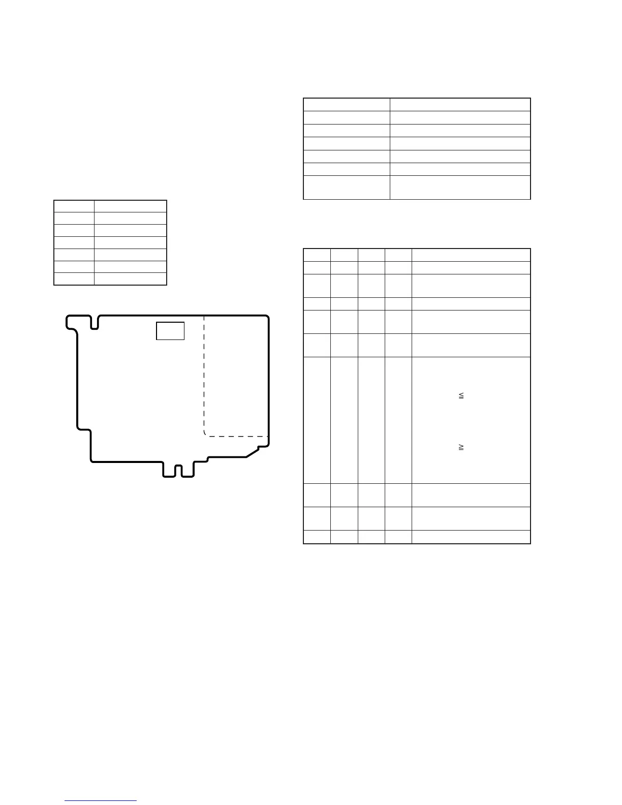
Fig. 5-1-17.
PD-148 board
Inverter
transformer
unit
CN2105
16