5-26
Address
70
71
72
73
74
75
76
77
78
79
7A
7B
7C
7D
7E
7F
80
81
82
83
84
Data
EC
0F
FB
0C
46
0B
0F
0A
03
09
78
48
CB
76
4F
83
8E
82
25
6F
1E
Address
23
24
25
26
Data
9C
A3
A5
AC
13.Mechanical Shutter Adjustment
(DCR-PC9/PC9E)
Adjust the period which the mechanical shutter is closed, and
compensate the exposure.
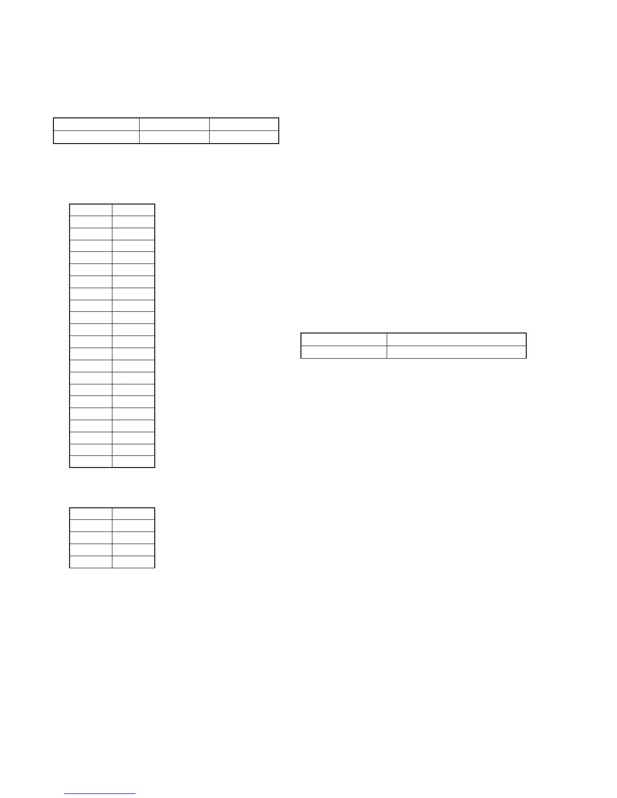
Adjustment Page F 7
Adjustment Address 70 to 84 23 to 26
Input method:
1) Select page: 0, address: 01, and set data: 01.
2) Input the following data to page: F, addresses: 70 to 84.
Note: Press the PAUSE button of the adjustment remote commander
each time to set the data.
RadarWRadarWRadarWRadarWRadarW
3) Input the following data to page: 7, addresses: 23 to 26.
Note: Press the PAUSE button of the adjustment remote commander
each time to set the data.
4) Select page: 0, address: 01, and set data: 00.
14. Angular Velocity Sensor Sensitivity Adjustment
• This adjustment is performed only when replacing the angular
velocity sensor.
Although this adjustment need not be performed when the circuit
is damaged, etc., check the operations.
• Note down the sensitivity displayed on the angular velocity sensor
of the repair parts. At this time, note down also to which board it
was attached to.
Be sure to check because if attached incorrectly, the screen will
vibrate up and down or left and right during hand-shake correction
operations.
Precautions on the Parts Replacement
There are two types of repair parts.
Type A: ENC03JA
Type B: ENC03JB
Replace the broken sensor with a same type sensor. If replace with
other type parts, the image will vibrate up and down or left and
right during hand-shake correction operations. After replacing, re-
adjust according to the adjusting method after replacement.
Precautions on Angular Velocity Sensor
The sensor incorporates a precision oscillator. Handle it with care
as if it dropped, the balance of the oscillator will be disrupted and
operations will not be performed properly.
Adjustment Page F
Adjustment Address 66, 67
Note1: The sensor sensitivity of SE3450 and SE3451 of the CF-085 board
is written only on the repair parts.
Adjusting method:
1) Select page: 0, address: 01, and set data: 01.
2) Read the sensor sensitivity written on SE3450 (PITCH sensor)
of the CF-085 board, and take this as S3450.
3) Read the sensor sensitivity written on SE3451 (YAW sensor)
of the CF-085 board, and take this as S3451.
4) Calculate D66’ and D67’ using the following equation (decimal
calculation).
NTSC model (DCR-PC9)
D66’ = 56 / S3450
D67’ = 64 / S3451
PAL model (DCR-PC6E/PC9E)
D66’ = 78 / S3450
D67’ = 78 / S3451
5) Convert D66’ and D67’ into hexadecimal digits, to obtain D66
and D67. (Round off decimal points)
6) Select page: F, address: 66, set data: D66, and press the PAUSE
button of the adjustment remote commander.
7) Select page: F, address: 67, set data: D67, and press the PAUSE
button of the adjustment remote commander.
Processing after Completing Adjustments
1) Select page: 0, address: 01, and set data: 00.
2) Check that the steady shot operations have been performed
normally.